|
加载中,请稍候...
|
|
A-Failure-Tolerant-CANopen-System-for-Marine-Automation-Systems
关键词:
|

|
|
简介:A Failure-Tolerant CANopen System for Marine Automation Systems by K. Etschberger, R. Hofmann, A. Neuner, U. Weissenrieder, B. Wiulsroed Abstract CANopen-based communication also becomes popular for failure-tolerant systems. A typical application of that type is the area of marine automation systems, e.g. ship alarm, monitoring and control systems in any kind of ships like product carriers, c... |
|
品 牌
|
|
|
|
产 地
|
|
|
型 号
|
PXF3028
|
|
折 扣
|
|
|
咨询专家:
|
产品说明:
A Failure-Tolerant CANOpen System for Marine Automation Systems
by K. Etschberger, R. Hofmann, A. Neuner, U. Weissenrieder, B. Wiulsroed
Abstract
canopen-based communication also becomes popular for failure-tolerant systems. A typical application of that type is the area of marine automation systems, e.g. ship alarm, monitoring and control systems in any kind of ships like product carriers, container ships, passenger vessels, ferries and cargo ships. The main rule to be met in that type of application is, that the system must tolerate at least one arbitrary single component failure. This implies that a general redundant system configuration, including the communication system, has to be provided to fulfill the requirements of a failure-tolerant system. This article describes a CANOpen-based communication system that fulfills the requirements of a failure-tolerant system. It was developed by ixxat Automation for the Norwegian ship automation systems supplier Kongsberg Norcontrol. The system already operates very successfully in many applications. The implemented system concept is now established as the basis for a CANOpen-based standard in ship automation (CiA SIG Maritime Electronics).
Introduction
Today, modern ships are multifunctional plants with a number of process segments like power management, engines and generators, cargo pumps and valves, ballast, bunker and cargo tanks. This requires the access of up to thousands of I/O-points per process segment. Large scale systems may comprise up to 20.000 I/O-points. The large amount of data and various system functions makes it necessary to implement this type of system in form of a hierarchical and modular structured architecture with decentralized intelligence. To facilitate data collection, similarly to other fields of automation, an appropriate data communication system is required.
In addition to common requirements such as reasonable costs, ship automation systems must also satisfy increased safety conditions as claimed by the registration procedures of the different classification societies. Since the data communication model of modern automation systems takes a major part of such systems, they need to meet the safety requirements as well.
 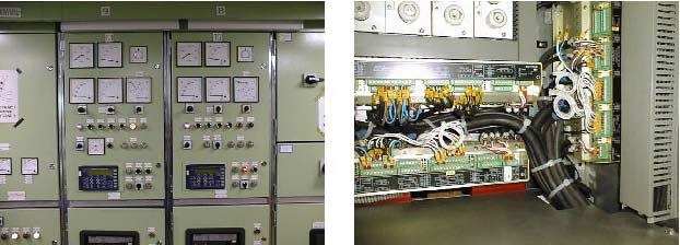
Fig. 1: Monitoring and control of automation subsystems in large scale systems may comprise 20.000 of I/O-points. Photo: Kongsberg Norcontrol (first; Berge Nord, second & third; Main switchboard outside & inside)
Therefore the data communication system has to be failure-tolerant, too. Besides the safety requirements further increased demands result from the harsh environment and the high reliability demands of the ship application.
The following introduces the system concept of the implemented ship automation system, based on an extension of the canopen standard. CANOpen was selected due to its unique features, like:
-
Based on the proven, robust physical and data link of CAN, the data communication system provides high reliability, high error tolerance and error detection capability [1]
-
Microcontrollers with integrated CAN-controllers make a very cost effective implementation of the network connectivity possible
-
With CANOpen an already widely established and supported standard is available, which provides a very sophisticated solution for implementation of distributed automation systems. It provides standard communication features according to the producer-consumer model as well as the clientserver-model of communication, network management and system services and a standardized method for the description of devices [1], [2], [3], [4],[5].
-
The extension of the existing CANOpen standard according to the specific requirements of a failure-tolerant communication are straightforward
System Structure and System Components
Fig. 2 shows a typical system structure of the NORCONTROL ship automation system.
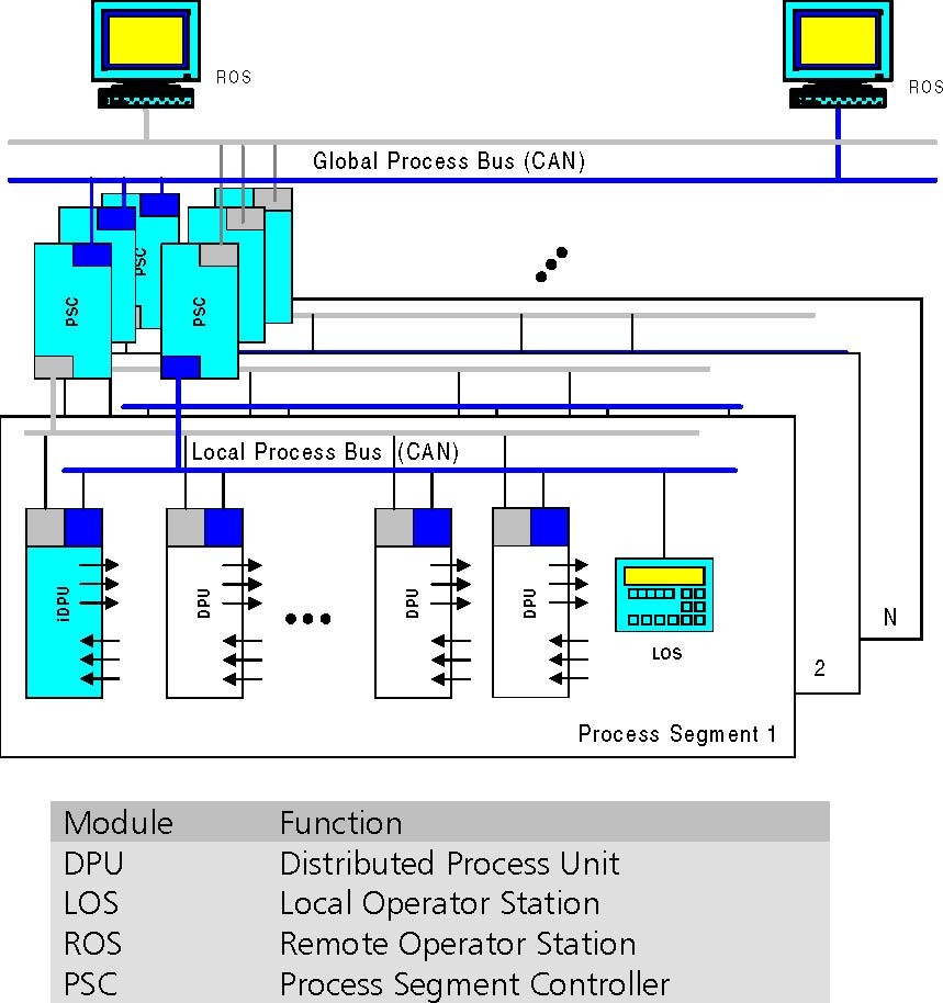
Fig. 2: Typical system structure of the NORCONTROL ship automation system
The basic idea of the shown system structure is the partitioning of the system into several process segments. In a process segment dedicated subsystem functions are integrated like power management, pumps and valve or auxiliary systems. Based on the processing capability of the distributed units process segments are independent from the rest of the system even when isolated from the rest of the system. The exchange of data within each process segment is based on a local communication system (local process bus). A global process bus connects the different process segments with the Remote Operator Stations. Thereby the subsystems are connected to the global bus by so-called “Process Segment Controllers” (PSC). These provide a bridge function between the subsystem and the global bus. Both types of communication systems are implemented in form of redundant canopen-based networks1. Due to the CANOpen protocol the maximum number of nodes per process segment is 127. At a data rate of 125 kBit/s a bus may extend up to 500 meters, at a data rate of 250 kBit/s the maximal distance is about 250 meters, due to the restrictions of the CAN protocol.
1 In an alternate system configuration Norcontrol also provides the possibility of connecting the Remote Operator Stations to the Global Process Bus via System Gateways. The connection between Remote Operator Stations and System Gateways is based on a redundant Ethernet-TCP/IP network.
Next a description of the different system components is given:
The Distributed Processing Units
The physical process interfacing and the remote processing such as monitoring and control of the subsystem are provided by means of Distributed Processing Units (DPU)
DPUs are available in different versions in form of digital and analogue input and output modules of different data width (16/32 bits) for digital modules, respectively different number of channels (8/16) in case of analogue modules. Specific system functions are provided by means of dedicated DPUs like units for Generator Control & Protection. Fig. 3 shows a DPU for Analogue Inputs.

Fig. 3: DPU for 16 channel Analogue Input (Photo: NORCONTROL)
DPU modules are based on the Infineon C167 microcontroller with two CAN interfaces. The modules provide a standard canopen interface [6] and are completely configurable via the CAN bus. Due to their rugged design they may be used directly in the harsh environment of a ship’s machine room or directly mounted onto the engines. The modules boot manager software allows updating of the module software via the CAN bus. Module configuration data is stored on flash memory or EEPROM, respectively. With each power-up the boot manager performs a self-test routine. For testing purposes each module furthermore provides a simulation mode, which can be activated via the CAN bus. Access to module configuration parameters is password protected.
In addition to the process interfacing function of normal DPUs, the so-called “Intelligent Distributed Processing Units” provide data processing capability based on programmable logic functions. These modules are also able to operate as so-called “MMI-Server” for simple operator interfaces (LOS) (will be explained later).
The Remote Operator Station (ROS)
The PC/Windows NT-based Remote Operator Station (ROS) provides supervisory control and monitoring function for the system including a sophisticated graphical man-machine interface (MMI). A ROS is connected to the CAN bus via an intelligent CAN Interface board (ixxat Automation). This interface provides the complete standard CANOpen master functionality including several additional network and system services in form of a Windows-NT DLL for the PC-based CAN-Interface-Server (CIS). The additional network functions comprise system configuration, controlling the system master determi
nation process, MMI scanning, SDO management function and provision of a global system time. These functions will be explained later. The CAN-Interface-Server initializes the network after power up and provides a data interface to the remote modules by means of a data base. Via this data base the different ROS client applications have access to the remotely collected data of the system. A further function of the CIS is the provision of a sophisticated test and simulation interface.
In connection with the DPU’s simulation mode it is possible to facilitate system installation.
The Local Operator Station (LOS)
Main purpose of the LOS devices (Local Operator Station) (Fig. 4) is to enable local access to the intelligent DPUs for inspection of process variables, local operation or process equipment, simulation of input/output signals, adjustment of parameters and inspection of the built-in diagnosis. In small system configurations without a Remote Operator Station, the LOS can be used as the main operator station.
LOS devices may be stationary mounted or dynamically inserted into the communication system by a service technician. LOS devices itself are only able to read the keyboard and display messages on the LC-display. Accessing a DPU module is coordinated by an MMI-server. The MMI client-server relationship will be explained later.
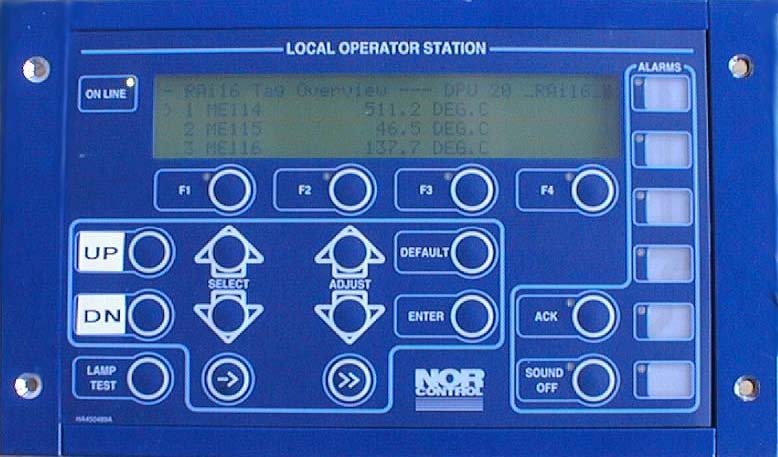
Fig. 4: Low Cost Operator Station (Photo: Norcontrol)
Transmission of Process Data
According to the canopen standard the transmission of real-time or process data is based on so-called “Process Data Objects” (PDOs). This type of communication objects provide a very efficient usage of the available transmission bandwidth, since it is based directly on the OSI-layer-2 transmission protocol. Within one frame up to 8 bytes of data may be transmitted. PDO communication works according to the producer-consumer model. This means that a transmitted PDO is available to any other nodes in the network. PDOs are identified by a unique 11-bit message identifier. The meaning and assembling of the data transmitted within a PDO is described in a “Device´s Object Dictionary”. To extend the number of items to be distinguished, a multiplexed usage of PDOs was introduced. To accomplish this, the first two data bytes of the PDO data field are used as a “tag” for specifying the following data. This allows to transmit up to 65 536 different items with only one PDO or CAN-identifier, respectively2. The main usage of tagged data is the transmission of process variables of dif
2 Later the principle of PDO multiplexing was introduced in generalized form also into the CANOpen-standard DS 301 Annex A, in form of the so-called “Multiplexed PDO”
ferent types. The transmission of PDOs occurs event-controlled (“asynchronous PDO”) with a maximum data rate of 10 messages/sec for a PDO. Normal PDOs for transmitting of direct I/O data use CAN-identifiers according to DS 401 (Default-PDOs), multiplexed PDOs use specific identifiers based on the module-ID. I/O-modules generally use up to four default PDOs, two multiplexed Transmit-PDOs and dependent of the module type a different number of multiplexed Receive-PDOs.
Transmission of Parameter and Diagnostic Data
A client-server communication channel between two devices may be established by means of canopen Service Data Objects (SDOs).
This type of communication is used to access the Object Dictionary of a device e.g. for configuration of device parameters, reading of diagnostic data, triggering of device functions or downloading of a software update to a device. An Object Dictionary Entry is specified by its 16-bit index and 8-bit subindex. Since the SDO-protocol supports fragmentation, the number of bytes transmitted is practically unlimited.
Network and System Management
As an essential part of any distributed system, CANOpen provides services for network and system management. Typically, network management functions support the boot-up of a network3 and provide node guarding. System management comprises standardized emergency messaging, system-wide time synchronization, configuration services and the SDO-manager facility.
In the Norcontrol system the system managment also provides a NMT scanning function. This function cyclically scans the network for new nodes connected to the network, identifies new nodes and checks the configuration parameter of the node against the data stored in a system data base. For checking of the validity of device parameters, only a specified object dictionary entry has to be checked. This entry contains date and time of the last parameterization and is checked against the data of the system data base. If the data does not match, the device will be parameterized automatically with the configuration data stored in the data base. Using this method, plug-and-play of devices is provided4. For node guarding, a network management instance (NMT master) cyclically polls any node in the network to check if nodes still are able to communicate5. With the CANOpen node guarding protocol also a node checks if the NMT-master still is alive.
The configuration of node number and setting of the baud rate via the CAN-bus is supported by means of the CANOpen LMT services and protocols6. Therefore setting of DIP-switches, which is not very appropriate in the environment of ship automation, is not necessary.
3 In version 3.0 of DS 302 a standardized boot-up procedure will be specified, which provides plug and play capability
4 Prerequisite for this is the prior setting of data rate and node-ID. This usually is performed by means of a service tool in a 1:1 connection to the module using LMT services.
5 An alternative method according to CANOpen Specification DS 301, Version 4 is based on the so-called “heartbeat” message transmission. Thereby the nodes cyclically transmit a “heartbeat”-message. 6 In DSP 305, Version 1 the equivalent services are called Layer Setting Services (LSS )
Another very important feature of a canopen-based system are standardized emergency messages. By means of an emergency message, a device may inform any other node about the occurrence and reason of a device-internal failure or error condition.
To provide a system-wide synchronized time, CANOpen provides a high resolution time protocol. Therefore, a synchronization server provides a high priority synchronization message, followed by a second message which provides the exact point of time when the synchronization message was sent. With this information, the other modules are able to synchronize their local time reference with high accuracy to the system wide time reference. In the Norcontrol system the system-wide time reference is used for analyzing of alarm messages, issued by the different intelligent nodes distributed in the system. Thereby, across the network a maximum time difference of less than 1 ms can be provided, including transferring of the time messages across the process segment controllers.
In the Norcontrol system also another option of a CANOpen system, the SDO manager facility has been implemented. This facility provides to the system the capability for dynamic establishment of SDO-channels between devices. This feature allows to operate several LOS devices independently on the same network and to use the provided MMI server facility of a system manager device by the Local Operator Stations.
A node which provides the NMT master, SDO manager and optional system configuration capability is called a “CANOpen Manager” according to the CANOpen terminology. In Fig. 5 the main additional functions of a CANOpen or system manager, as implemented in the Norcontrol system is shown. The system manager function may be executed by any one of the ROS, PSC or LOS devices. With respect to the system manager function, the different device types have different priority classes, with a ROS having the highest. Since at any time, only one node is allowed to perform as CANOpen manager, a “Master Determination Process” is required. Since failure of the active system manager would have serious impact on the data communication system, the system master functionality has to be provided in redundant form. If the active CANOpen manager fails, this function is automatically switched to another node which is able to perform system management. This process is called “Flying Master Process” and will be described later.
|
NMT-Master
|
SDO-Manager
|
Emergency Consumer/ Producer
|
|
NMT Scanner
|
Sync Producer
|
ConfigurationManager (only ROS)
|
|
MMI Scanner
|
System Time Producer
|
Flying Master Capability
|
Fig. 5: Additional communication-related functions of system management capable devices (ROS, PSC, LOS)
Redundancy Concept
The general requirement for single failure tolerance in ship automation systems means, that not only major system components like pumps or valves have to be provided twice, but also requires a redundant data communication system. Therefore, the Norcontrol data communication system provides two pairs of CAN bus line with a system manager on each bus possible.
As a major measure, the communication ability of each device of a network is monitored continuously by means of the canopen life guarding mechanism7. According to this protocol, the NMT master instance cyclically polls the communication status of each device after expiration of a predefined “guard time”. The device (NMT slave instance) has to respond within the “node life time”. If the device fails to respond within that time, the NMT master will indicate a “node guarding event” to its application. On the other hand, if a device does not receive a status request during its “life time” from the NMT master, the NMT slave issues a “life guarding event” to its application. A typical value for the guard time is 1 second.
For transmission of PDOs the following rules apply:
-
PDO transmitting devices send a PDO on both CAN buses with the same COB-identifier and data tag. To secure the transmission of both PDOs in the same time window, the time of transmission of a PDO is continuously watched. If the transmission of a certain PDO on a bus line is delayed more than a maximum allowable time interval against the transmission on the other line, the transmitting PDO queue of the other bus line is copied into the delayed queue. Synchronizing of the transmit PDO queues also occurs in case of a transmit queue overrun. Any queue resynchronization is signaled on the bus by transmission of an emergency message.
-
PDOs are received on both CAN-buses. The received data is stored into the corresponding Object Dictionary entries.
Emergency messages are handled like PDOs.
Data transmission via SDO channels is independent on both CAN lines.
Since the standard object dictionary of the devices has usually only one set of SDO client and server entries for identifiers used by the SDOs, the redundant bus architecture provides an own set of client and server SDO entries for each side.
Therefore the dynamic establishment of SDO channels works without interfering with the other CAN line.
Determination of the active CANOpen manager
In a system, it is possible to have more than one manager-capable devices like ROS, PSC and LOS in a network. It is therefore necessary to provide a process, by which automatically one of the manager-capable devices becomes the active system manager. Also, in case of a failure of the currently active system manager an automatic determination of another manager-capable device has to be performed. Fig. 6 shows the master determination process at a ROS device.
7 Alternatively CANOpen, Version 4 respectively SIG Maritime Electronics specifies a heartbeat protocol for life guarding between a heartbeat producer and heartbeat consumers.
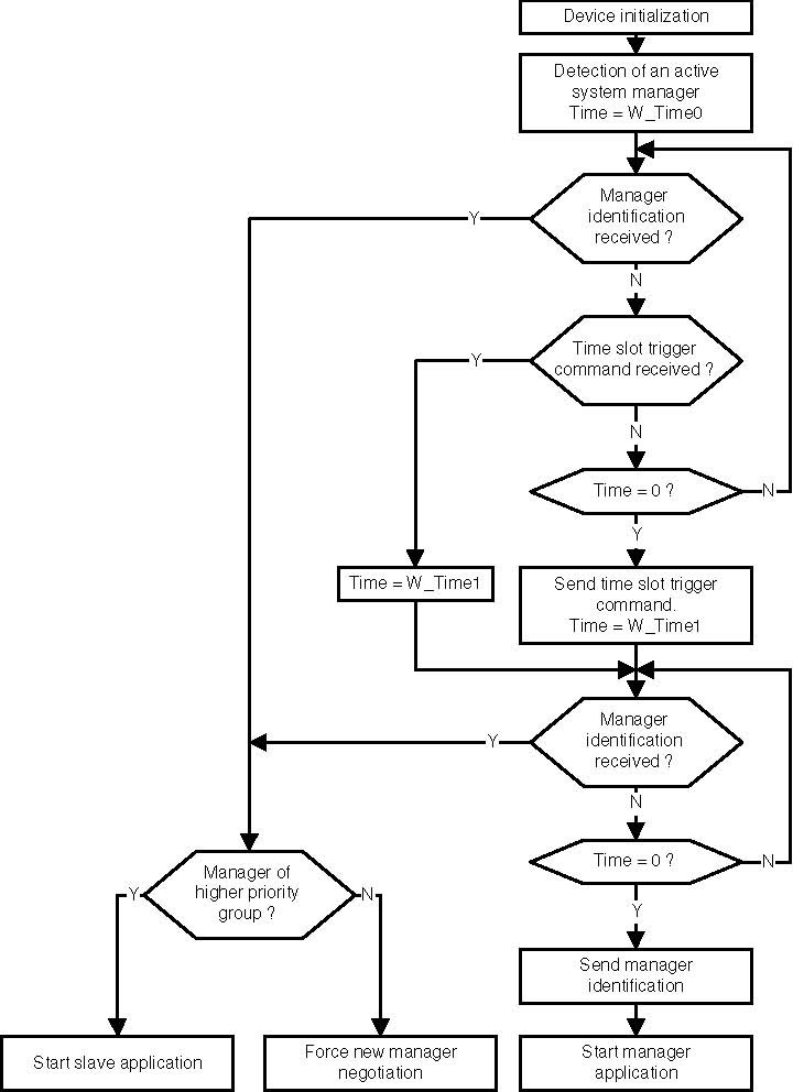
Fig. 6: Master determination process
A device with manager capability connected to the network first has to check if there is already a canopen manager active. Therefore the device transmits a “manager-identification request” (reserved identifier, no data) and waits for the answer of an active manager. An active manager responds by transmitting an “manager-identification” object (reserved identifier, manager priority and module-Id in the data field). If the device receives a manager identification with a priority higher than its own, the device accepts the currently active master and starts its slave application. If the priority of the currently active manager is lower, the newly connected device forces a new manager determination process by transmitting a NMT reset communication command with a module ID equal to 0.
If no manager answers during a predefined response time the device to be connected starts a system manager determination cycle by transmitting a “time slot trigger command”. Devices with manager capability start their local timer after reception of this command. The local timer stops after a time which depends on the priority and module number of the devices. If after the timeout no master identification occurred, the device becomes the system manager and transmits its manager identification (Fig. 7).
Reset
timeslot trigger master-
Communication
identification
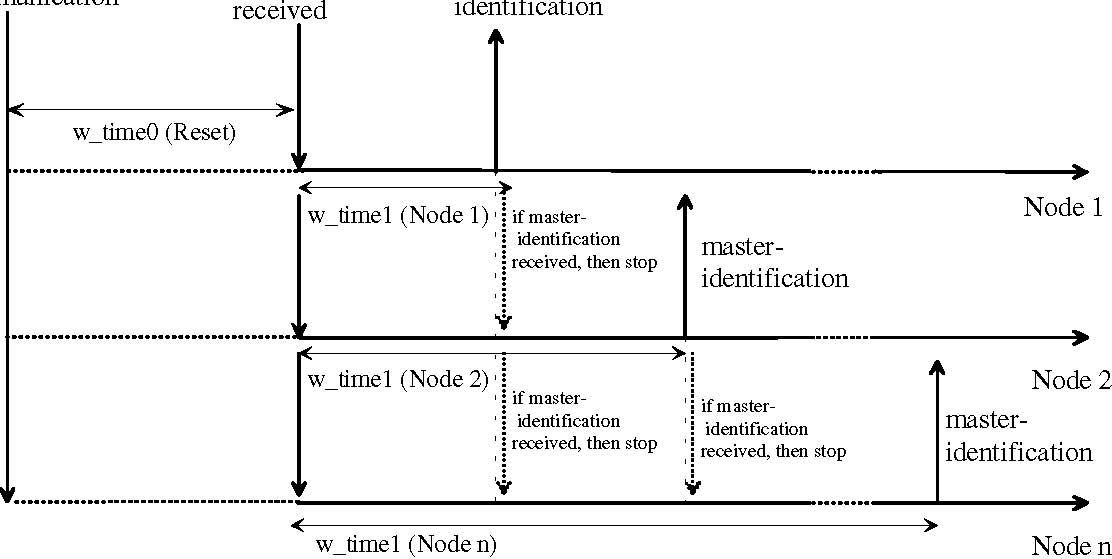
|
w_time1 (Node 1)
|
if master
|
|
|
identification
|

|
received, then stop
|
|
w_time1 (Node 2)
|
if master
|
|
|
identification
|
|
|
received, then stop
|
Node n
Fig. 7: System manager determination protocol
The Process Segment Controller (PSC)
As mentioned previously, the basic system architecture is characterized by several functional subsystems connected to a system bus by means of a so-called “Process Segment Controller” PSC. This type of system architecture provides several advantages:
-Problems in a subsystems do not have an impact on the rest of the system -Each process segment represents a separate CAN bus, extending the possible bus length accordingly, -Within the functional subsystems most data communication is local. This results in a reduced bus load, reduces the required data rate and decreases the latency time of messages, respectively. -Connection of up to 127 devices per subsystem is possible8
The main function of the PSC is a bridge function9. PDOs which are only of local relevance are not passed across the bridge. There is a variety of further functions the PSC has to provide (Fig. 8), e.g. bridging of SDO-message from the system bus onto the relevant subsystem bus or passing the system time from the system bus to the subsystem bus. Of course, the PSC has to keep two object dictionaries and to support the functions of the system manager if required. The PSC is implemented on a microcontroller Infineon C167 and provides two CAN interfaces.
8 The subsystem is specified for up to 20 DPUs and 20 LOS modules at present. 9 Passing of PDOs from one network to the other requires a conversion of the PDO identifiers.
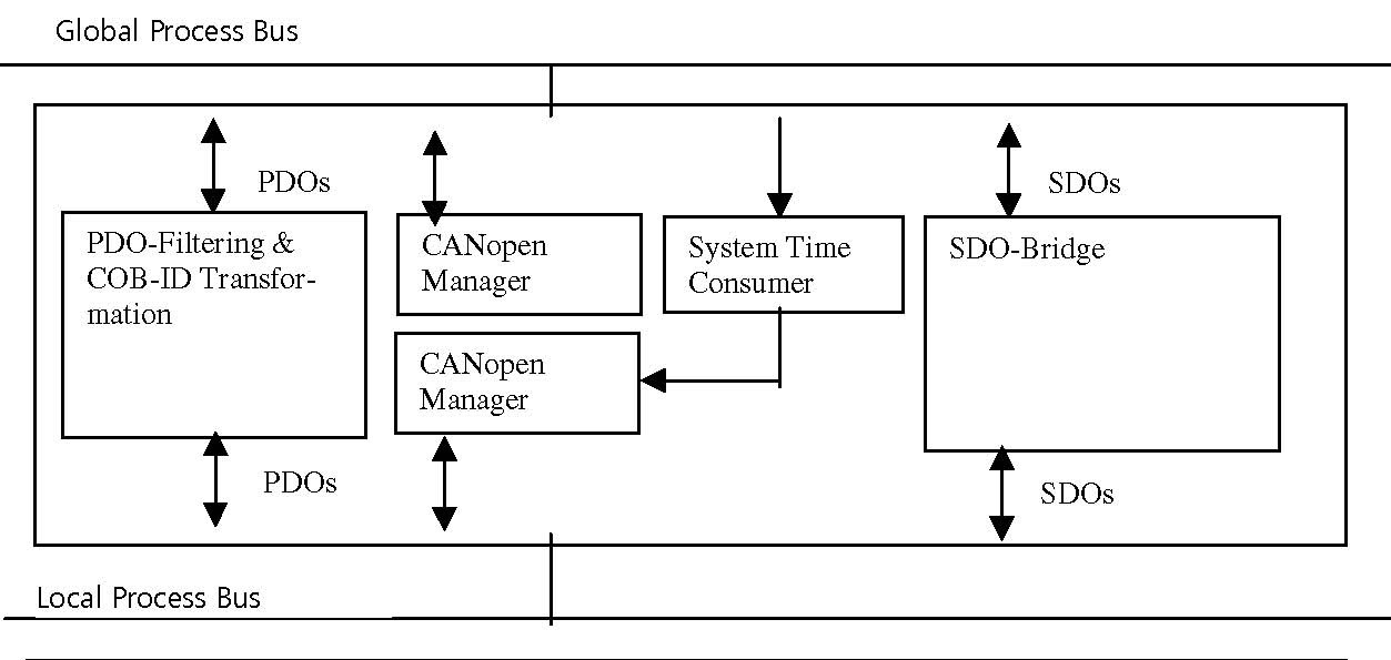
Fig. 8: Functionality of a Process Segment Controller
The MMI-Client-Server System
The Local Operator Stations (LOS) provide a low cost operator interface to the Distributed Processing Units of a process segment. Access to the data of the intelligent DPU modules is provided by establishing a canopen SDO channel between a LOS and the Object Dictionary of a corresponding DPU. Since it should be possible, that at the same time access from several LOS devices to the Object Dictionary of an intelligent DPU may exist and also the system configuration might be changed, a dynamic establishment of SDO channels is implemented. Therefore the system has to provide a CANOpen SDO manager facility. To allow a very flexible system configuration the functionality of the operator panel is not fixed in the LOS device but provided by so-called “MMI-server” instances. With the MMI server feature an intelligent device provides its data to any of the MMI-clients in the network. The dynamic connection of devices is supported by the so-called “MMI scanner” which cyclically scans the network for new connected MMI clients and servers. If a new server is found, this is reported to any existing MMI clients in the network, if a new MMI client is found, this is reported to any already known servers. If a connection between a LOS and a specific intelligent DPU is selected by an operator, first an SDO channel is established between the MMI client and server of the connected device and vice versa. The functionality of the LOS is then provided by the remote MMI-server. That means, when a button is pressed on the LOS this event is sent to the MMI server via an SDO message. The MMI server then interprets the request and responds with the requested function or data. With the described client-server concept a very high flexibility is achieved in respect to future extensions of the DPUs functionality and modifications of the operator panel menue. In addition, software updates are concentrated to the MMI server units.
Summary
With the developed automation system based on CAN/canopen, a very cost effective, modular system of high flexibility and capability is available, which also fulfills the specific safety requirements of ship automation. The system already is in operation successfully in many applications.
The underlying hierarchical system architecture and partitioning of the system into several subsystems provides important advantages with respect to reduced failure interaction, reduced bus load and increased maximum number of devices.
CAN and CANOpen has been proven to be a very suitable platform also for the implementation of a very sophisticated, safety relevant communication system. The only necessary extension of the standard was the introduction of a mechanism for automatic master determination according to the “flying master” principle. In the data communication system also the optional management functions according to the framework for programmable devices [3] like SDO- and configuration management as well as provision of a system-wide high resolution time reference have been implemented successfully. The developed system solution will be the main input for the ongoing development of an application standard by the SIG Maritime Electronics.
Literature
[1] K. Etschberger, Controller-Area-Network, Grundlagen, Protokolle, Bausteine, Anwendungen. Hanser-Verlag 2000, ISBN3-446-19431-2 (English Edition available Q4/2000)
[2] CIA DS 301: CANOpen Communication Profile for Industrial Applications, Version 4.01, June 2000
[3] CIA DS 302: Framework for Programmable CANOpen Devices, Version 3.0, June 2000
[4] CIA DS 401: CANOpen Device Profile for I/O Modules, Version 2.0, December 1999
[5] CIA DSP 305: Layer Setting Services and Protocol, Version 1.0, May 2000
[6] ixxat, CANOpen Master/Slave Software Description, May 2000
Authors
Prof. Dr.-Ing. K. Etschberger, R. Hofmann, A. Neuner, U. Weissenrieder, ixxat Automation, Leibnizstraße 15, 88250 Weingarten, www.Ixxat.de
B. Wiulsroed, Kongsberg Norcontrol, P.O Box 1009, N-3194 Horten, Norway, www.norcontrol.no
canopenixxat
参数资料:
|
A-Failure-Tolerant-CANopen-System-for-Marine-Automation-Systems


|
价格列表:
A-Failure-Tolerant-CANopen-System-for-Marine-Automation-Systems
| 葩星订货号 |
订货号 |
产品名称 |
报价 |
品牌 |
|
| PXO_2752 | 3.5KW,BDA035 | 3.5KW,BDA035 | 5482 | ~ | 7005 | etherrt |  |  |
|
|
相关产品:
A-Failure-Tolerant-CANopen-System-for-Marine-Automation-Systems |
|
|
|
|
 收藏灵猫网
收藏灵猫网