|
加载中,请稍候...
|
|
ALR111,-ALR121
关键词:
|
|
|
简介:> >Models ALR111, ALR121 General Serial Communication Specifications Modules (for FIO) GS 33K50G10-50E •GENERAL This document describes about Models ALR111 and ALR121 Serial Communication Modules (for FIO) that a field control station (FCS) uses to perform serial communication with subsystems such as FA-M3. These serial communication modules can be mou... |
|
品 牌
|
|
|
|
产 地
|
|
|
型 号
|
PXF3280
|
|
折 扣
|
|
|
咨询专家:
|
产品说明:
<<Contents>> <<Index>>
 Models ALR111, ALR121 Models ALR111, ALR121
General
Serial Communication
Specifications
Modules (for FIO)
GS 33K50G10-50E

• GENERAL
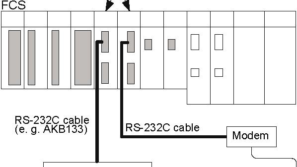
This document describes about Models ALR111 and ALR121 Serial Communication Modules (for FIO) that a field control station (FCS) uses to perform serial communication with subsystems such as FA-M3. These serial communication modules can be mounted on field control units (AFV30, AFV40, AFV10, and AFF50), ESB bus node unit (ANB10), optical ESB bus node unit (ANB11), and ER bus node unit (ANR10).
ALR111 communication module
Subsystem
Modem
(e. g. FA-M3)
RS-232C cable

Subsystem
(e. g. FA-M3)
F01E.ai
Figure A Configuration Sample of the Serial Communication Modules

|
Yokogawa Electric Corporation
|
GS 33K50G10-50E
|
|
2-9-32, Nakacho, Musashino-shi, Tokyo, 180-8750 Japan
|
©Copyright Aug. 2011(YK)
|
|
Tel.: 81-422-52-5634 Fax.: 81-422-52-9802
|
3rd Edition Apr. 1, 2013(YK)
|
<<Contents>> <<Index>>
• HARDWARE SPECIFICATIONS
The serial communication modules (ALR111 and ALR121) hardware specifications are as shown below.
Table Serial Communication Module Hardware Specifications
|
Item
|
Specifications
|
|
Model
|
ALR111
|
ALR121
|
|
Interface
|
RS-232C
|
RS-422/RS-485
|
|
Connection method
|
Point-to-point
|
Point-to-point (RS-422) Multipoint (RS-485)
|
|
Communication function
|
Half-duplex
|
|
Synchronization method
|
Start-stop synchronization
|
|
Transmission speed
|
1200/2400/4800/9600/19200/38400 bps (*1)
|
|
Transmission code
|
ASCII/binary
|
|
Character length
|
7/8 bits
|
|
Stop bit length
|
1/2 bits
|
|
Parity check
|
None/even/odd
|
|
Lag time after data transmission
|
1 ms (The lag time to start receiving data again after data transmission.)
|
|
Transmission distance
|
Maximum 15 m
|
Maximum 1200 m (total extended length)
|
|
Installation method
|
Mounted on ANB10, ANB11, ANR10, AFF50, AFV10, AFV30, or AFV40□
|
|
I/O wiring
|
AKB131, AKB132, AKB133, AKB134 cables, etc.
|
Cable with 3-pair shield, AKB161, or AKB162
|
|
Wiring connection
|
D-sub-9-pin (female x 2)
|
Clamped with terminal block’s M4 screws (5 poles x 2)
|
|
Current consumption
|
0.5A
|
|
Weight
|
0.3 kg
|
0.3 kg
|
*1: The applicable transmission speed depends on the communication function, subsystems, and connection method.
An FCS collects data from subsystems or sets data with control calculations to subsystems using the builder functions by way of serial communication modules. A communication module selects only one communication function, thus two ports must have identical communication functions. It is not possible to select different communication function for every port. The communication functions and those transmission speeds for each communication module are as shown in the table below.
Table Communication Functions for Communication Modules
|
Communication function
|
ALR111
|
ALR121
|
|
FA-M3 communication
|
DR
|
DR
|
|
modbus communication
|
DR
|
DR
|
|
MELSEC-A communication
|
DR
|
DR
|
|
YS communication with direct connection
|
NIL
|
SG
|
|
YS communication
|
NIL
|
SG
|
|
SLC500 communication
|
SG
|
SG
|
|
PLC-S communication
|
SG
|
SG
|
DR: Dual-redundant communication is applicable. SG: Only single communication is applicable. NIL: Not complied
Table Transmission Speed by the Communication Function
|
Communication function
|
Transmission speed (bps)
|
|
FA-M3 communication
|
1200/2400/4800/9600/19200/38400 (*1)
|
|
Modbus communication
|
1200/2400/4800/9600/19200
|
|
MELSEC-A communication
|
1200/2400/4800/9600/19200
|
|
YS communication (direct connection)
|
9600
|
|
YS communication
|
9600
|
|
SLC500 communication
|
1200/2400/4800/9600/19200
|
|
PLC-S communication
|
1200/2400/4800/9600/19200
|
*1: The transmission speed of 38400 bps is not available for some PC link modules.
<<Contents>> <<Index>>
• OPERATING ENVIRONMENT
Hardware Requirements
The serial communication module runs on the following FCS. AFV30S, AFV30D, AFV40S, AFV40D, AFV10S, AFV10D, AFS30S, AFS30D, AFS40S, AFS40D, AFG30S, AFG30D, AFG40S, AFG40D, AFG81S, AFG81D, AFG82S, AFG82, AFG83S, AFG83D, AFG84S, AFG84D, AFF50S, AFF50D
Software Requirements
The serial communication module runs on the control functions of the following FCS. LFS1700 Control Function for Field Control Station (for AFV30/AFV40, Vnet/IP and FIO): for AFV30/AFV40□LFS1500 Control Function for Field Control Station (for AFV10, Vnet/IP and FIO): for AFV10• LFS1300 Control Function for Standard Field Control Station (for V net and FIO): for AFS30/AFS40□ LFS1330 Control Function for Enhanced Field Control Station (for V net and FIO): for AFG30AFG40/AFG8□ LFS1350 Control Function for Compact Field Control Station (for V net and FIO): for AFF50□
Engineering Requirements
Works on LHS5100/LHMS5100 Standard Builder Function.
• INSTALLATION ENVIRONMENT
LFS1700 Control Function for Field Control Station (for AFV30/AFV40)
|
No. of ALR111/ALR121/ALE111/ALP111 or ALP121/ AGS813/AGP813 modules
|
Max. 8 units/FCS (Max. 4 pairs for dual-redundant operation) (*1)
|
|
No. of ALF111 modules
|
Max. 30 units/FCS (Max. 15 pairs for dual-redundant operation)
|
|
No. of all the communication modules
|
Max. 30 modules/FCS (*1) (*2)
|
|
I/O data capacity for communication
|
1000 words/ALR111, 1000 words/ALR121
|
|
No. of communication definition
|
128 definitions/ALR111, 128 definitions/ALR121
|
|
No. of communication functions
|
Max. 8 types/FCS (*1) (*3)
|
|
Communication I/O data capacity
|
Max. 8000 words/FCS (incl. data from other communication function)
|
*1: ALP111 and ALP121 cannot be mounted on the same FCS together. *2: This is the sum of ALR111, ALR121, ALE111, ALF111, ALP111 or ALP121, AGS813, and AGP813 modules. *3: This is the sum of communication functions of ALR111, ALR121, ALE111, and ALP111 or ALP121.
LFS1700 Control Function for Field Control Station (for AFV30/AFV40) + LFS1750 Node Expansion Package (for 10 nodes)
|
No. of ALR111/ALR121/ALE111/ALP111 or ALP121/AGS813/AGP813 modules
|
Max. 16 units/FCS (Max. 8 pairs for dual-redundant operation) (*1)
|
|
No. of ALF111 modules
|
Max. 32 units/FCS (Max. 16 pairs for dual-redundant operation)
|
|
No. of all the communication modules
|
Max. 48 modules/FCS (*1) (*2)
|
|
I/O data capacity for communication
|
1000 words/ALR111, 1000 words/ALR121
|
|
No. of communication definition
|
128 definitions/ALR111, 128 definitions/ALR121
|
|
No. of communication functions
|
Max. 8 types/FCS (*1) (*3)
|
|
Communication I/O data capacity
|
Max. 8000 words/FCS (incl. data from other communication function)
|
*1: ALP111 and ALP121 cannot be mounted on the same FCS together. *2: This is the sum of ALR111, ALR121, ALE111, ALF111, ALP111 or ALP121, AGS813, and AGP813 modules. *3: This is the sum of communication functions of ALR111, ALR121, ALE111, and ALP111 or ALP121.
<<Contents>> <<Index>>
LFS1700 Control Function for Field Control Station (for AFV30/AFV40) + LFS1750 Node Expansion Package (for 14 nodes)
|
No. of ALR111/ALR121/ALE111/ALP111 or ALP121/AGS813/AGP813 modules
|
Max. 32 units/FCS (Max. 16 pairs for dual-redundant operation) (*1)
|
|
No. of ALF111 modules
|
Max. 64 units/FCS (Max. 32 pairs for dual-redundant operation)
|
|
No. of all the communication modules
|
Max. 64 modules/FCS (*1) (*2)
|
|
I/O data capacity for communication
|
1000 words/ALR111, 1000 words/ALR121
|
|
No. of communication definition
|
128 definitions/ALR111, 128 definitions/ALR121
|
|
No. of communication functions
|
Max. 8 types/FCS (*1) (*3)
|
|
Communication I/O data capacity
|
Max. 8000 words/FCS (incl. data from other communication function)
|
*1: ALP111 and ALP121 cannot be mounted on the same FCS together. *2: This is the sum of ALR111, ALR121, ALE111, ALF111, ALP111 or ALP121, AGS813, and AGP813 modules. *3: This is the sum of communication functions of ALR111, ALR121, ALE111, and ALP111 or ALP121.
LFS1500 Control Function for Field Control Station (for AFV10)
|
No. of ALR111/ALR121/ALE111/ALP111/AGS813/AGP813 modules
|
Max. 8 units/FCS (Max. 4 pairs for dual-redundant operation)
|
|
No. of ALF111 modules
|
Max. 30 units/FCS (Max. 15 pairs for dual-redundant operation)
|
|
No. of all the communication modules
|
Max. 30 modules/FCS (*1)
|
|
I/O data capacity for communication
|
1000 words/ALR111, 1000 words/ALR121
|
|
No. of communication definition
|
128 definitions/ALR111, 128 definitions/ALR121
|
|
No. of communication functions
|
Max. 4 types/FCS (*2)
|
|
Communication I/O data capacity
|
Max. 4000 words/FCS (incl. data from other communication function)
|
*1: This is the sum of ALR111, ALR121, ALE111, ALF111, ALP111, AGS813, and AGP813 modules. *2: This is the sum of communication functions of ALR111, ALR121, ALE111, and ALP111.
LFS1500 Control Function for Field Control Station (for AFV10) + LFS1550 Node Expansion Package (for AFV10)
|
No. of ALR111/ALR121/ALE111/ALP111/AGS813/AGP813 modules
|
Max. 16 units/FCS (Max. 8 pairs for dual-redundant operation)
|
|
No. of ALF111 modules
|
Max. 32 units/FCS (Max. 16 pairs for dual-redundant operation)
|
|
No. of all the communication modules
|
Max. 48 modules/FCS (*1)
|
|
I/O data capacity for communication
|
1000 words/ALR111, 1000 words/ALR121
|
|
No. of communication definition
|
128 definitions/ALR111, 128 definitions/ALR121
|
|
No. of communication functions
|
Max. 4 types/FCS (*2)
|
|
Communication I/O data capacity
|
Max. 4000 words/FCS (incl. data from other communication function)
|
*1: This is the sum of ALR111, ALR121, ALE111, ALF111, ALP111, AGS813, and AGP813 modules. *2: This is the sum of communication functions of ALR111, ALR121, ALE111, and ALP111.
LFS1300 Control Function for Standard Field Control Station (for AFS30/AFS40)
|
No. of ALR111/ALR121/ALE111 modules
|
Max. 6 units/FCS (Max. 3 pairs for dual-redundant operation)
|
|
Communication I/O data capacity
|
1000 words/ALR111, 1000 words/ALR121
|
|
No. of communication definition
|
128 definitions/ALR111, 128 definitions/ALR121
|
|
No. of communication functions
|
Max. 4 types/FCS (*1)
|
|
Communication I/O data capacity
|
Max. 4000 words/FCS (incl. data from other communication function)
|
*1: This is the sum of communication functions of ALR111, ALR121, and ALE111.
<<Contents>> <<Index>>
LFS1330 Control Function for Enhanced Field Control Station (for AFG30/AFG40/AFG8)
|
No. of ALR111/ALR121/ALE111/ALP111/AGS813/AGP813 modules
|
Max. 16 units/FCS (Max. 8 pairs for dual-redundant operation)
|
|
Communication I/O data capacity
|
1000 words/ALR111, 1000 words/ALR121
|
|
No. of communication definition
|
128 definitions/ALR111, 128 definitions/ALR121
|
|
No. of communication functions
|
Max. 4 types/FCS (*1)
|
|
Communication I/O data capacity
|
Max. 4000 words/FCS (incl. data from other communication function)
|
*1: This is the sum of communication functions of ALR111, ALR121, ALE111, and ALP111.
LFS1350 Control Function for Compact Field Control Station (for AFF50)
|
No. of ALR111/ALR121/ALE111/ALP111/AGS813/AGP813 modules
|
Max. 8 units/FCS (Max. 4 pairs for dual-redundant operation)
|
|
Communication I/O data capacity
|
1000 words/ALR111, 1000 words/ALR121
|
|
No. of communication definition
|
128 definitions/ALR111, 128 definitions/ALR121
|
|
No. of communication functions
|
Max. 4 types/FCS (*1)
|
|
Communication I/O data capacity
|
Max. 4000 words/FCS (incl. data from other communication function)
|
*1: This is the sum of communication functions of ALR111, ALR121, ALE111, and ALP111.
• Installations to the ER Bus Node Unit (*1) (*2)
No. of ALR111/ALR121/ALE111/ALF111/ALP111 modules: Max. 8 units
*1: Mounting on the ER bus node unit is applicable when the FCS’s main memory is 32 Mbyte or more and EB401 firmware revision is R3 or later.
*2: Field control units (AFV30□ and AFV40) do not support ER bus node unit (ANR10).
<<Contents>> <<Index>>
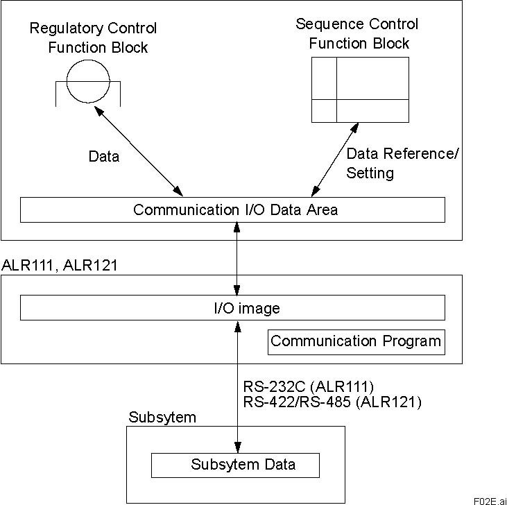
• SUBSYSTEM COMMUNICATIONS
The serial communication module communicates with subsystems at the specified intervals and stores the subsystem data in the communication modules’ I/O image area. FCS accesses the communication module asynchronously from them, and refers to or sets the I/O images. This enables FCS to use the subsystem data through the I/O terminals of the function block in the same way as the general analog and digital I/O signals.
FCS
Figure Flow of Data in a Subsystem
<<Contents>> <<Index>>
-
COMMUNICATION FUNCTIONS
-
FA-M3 Communication
Connected device: Personal computer link module F3LC11-1N, F3LC11-2N (FA-M3) LC01-0N, LC02-0N (FA500)
Connection method: Connect a personal computer link module with ALR111 or ALR121 communication port. Applicable device: FA-M3, FA500 Transmission protocol: FA-M3 dedicated control protocol No. of subsystem stations: Max. 30 stations/port
Table List of Applicable Devices
|
Device type
|
Device name
|
Communication capacity(per communication)
|
Read
|
Write
|
|
Bit device
|
Input relay
|
64 words
|
Y
|
N
|
|
Output relay
|
Y
|
Y
|
|
Internal relay
|
Y
|
Y
|
|
Shared relay
|
Y
|
Y
|
|
Link relay
|
Y
|
N
|
|
Special relay
|
Y
|
N
|
|
Time up relay
|
Y
|
N
|
|
Count up relay
|
Y
|
N
|
|
Word device
|
Decrementing timer current value
|
64 words
|
Y
|
Y
|
|
Incrementing timer current value
|
Y
|
Y
|
|
Timer set value
|
Y
|
N
|
|
Decrementing counter current value
|
Y
|
Y
|
|
Incrementing timer current value
|
Y
|
Y
|
|
Counter set value
|
Y
|
N
|
|
Data register
|
Y
|
Y
|
|
File register (*1)
|
Y
|
Y
|
|
Shared register
|
Y
|
Y
|
|
Index register (*2)
|
Y
|
Y
|
|
Link register
|
Y
|
N (*3)
|
|
Special register
|
Y
|
N
|
|
Special device
|
Communication time
|
1 word
|
Y
|
N
|
|
Communication status
|
Y
|
N
|
Y: Applicable
N: Not applicable *1: As for FA500, this is equivalent to the common register. *2: This device is for FA-M3. *3: FA-M3 is able to write data to other link devices than the one assigned to the local station; however, the data will be
overwritten upon refreshing by other stations.
<<Contents>> <<Index>>
• modbus Communication
Connected device: Serial transmission interface module
Connection method: Connect an ALR111 or ALR121 module communication port with serial transmission interface module
Applicable devices: By Yokogawa - STARDOM FCN, FCJ, and GC1000 Mark II (*1) By Schneider Electric - Modicon484, 584, 584L, 884, 984, 984A, 984B, 984X, and Micro 84 By Yasukawa Electric - Memocon-SC U84, 584, 684H, 694H, R84H-M, GL60S, and GL20
Transmission protocol: Modbus protocol (RTU mode) No. of subsystem stations: Max. 30 stations/port
*1: The communication with GC1000 Mark II is enabled via ASGW, and the number of port available for communication is one.
Table List of Applicable Devices
|
Device type
|
Device name
|
Communication capacity(per communication)
|
Read
|
Write
|
|
Bit device
|
Coil
|
125 words
|
Y (*2)
|
Y
|
|
Input relay
|
Y
|
N
|
|
Link relay (*1)
|
Y (*2)
|
Y
|
|
Step status (*1)
|
Y
|
N
|
|
Word device
|
Input register
|
125 words
|
Y
|
N
|
|
Maintenance register
|
Y (*2)
|
Y
|
|
Constant register (*1)
|
Y (*2)
|
Y
|
|
Step passing time (*1)
|
Y
|
N
|
|
Link register (*1)
|
Y (*2)
|
Y
|
|
Enhanced register (*1)
|
Y (*2)
|
Y
|
|
4-byte register
|
Y
|
N
|
|
Other device
|
Specific coil
|
1 word
|
Y
|
N
|
|
Communication status
|
Y
|
N
|
Y: Applicable
N: Not applicable *1: These devices are for Memocon-SC GL60S. *2: Data may not be readable depending on the functional codes.
<<Contents>> <<Index>>
• MELSEC-A Communication
Connected device: MELSEC-A computer link unit AJ71C24-S8/S6/S3, AJ71UC24, A1SJ71UC24-R2/R4/PRF, A1SJ71C24-R2/R4/PRF, A1SCPUC24-R2, A2CCPUC24 (PRF)
Connection method: Connect a computer link unit with ALR111 or ALR121 communication ports
Applicable devices: MELSEC-A CPU unit (A communication with FCS can be established with if a CPU is connectable with MELSEC-A computer link unit.)
Transmission protocol: MELSEC-A dedicated control protocol format 4 No. of subsystem stations: Max. 30 stations/port
Table List of Applicable Devices (*1)
|
Device type
|
Device name
|
Communication capacity(per communication)
|
Read
|
Write
|
|
Bit device
|
Input/output relay
|
32 words (512 points)
|
Y
|
Y
|
|
Internal relay
|
Y
|
Y
|
|
Latch relay
|
Y
|
Y
|
|
Step relay
|
Y
|
Y
|
|
Link relay
|
Y
|
Y
|
|
Annunciator
|
Y
|
Y
|
|
Special relay
|
Y
|
Y
|
|
Timer (contact, coil)
|
Y
|
Y
|
|
Counter (contact, coil)
|
Y
|
Y
|
|
Word device
|
Timer (current value)
|
64 words
|
Y
|
Y
|
|
Counter (current value)
|
Y
|
Y
|
|
Data register
|
Y
|
Y
|
|
Link register
|
Y
|
Y
|
|
File register
|
Y
|
Y
|
|
Special register
|
Y
|
Y
|
|
Other device
|
Communication status
|
1 word
|
Y
|
N
|
Y: Applicable
N: Not applicable
*1: For the communication with MELSEC-Q or QnA, it is possible to access the same device range as MELSEC-A via A-compatible communication mode. Access to the MELSEC-Q and QnA devices shown below is not applicable. Edge relay, accumulated timer (contact, coil, current value), special link relay, special link register, direct input, direct output, index register, file register, extended file register, latch relay, and step relay.
<<Contents>> <<Index>>
• YS Communication with Direct Connection (for ALR121 only)
Connected device: YS instruments (YS1000 SERIES and YS100 SERIES) Connection method: ALR121 communication port is connected with YS instruments via RS-485 cable. (*1)
*1: Set the YS instrument control cycle as 100 ms.
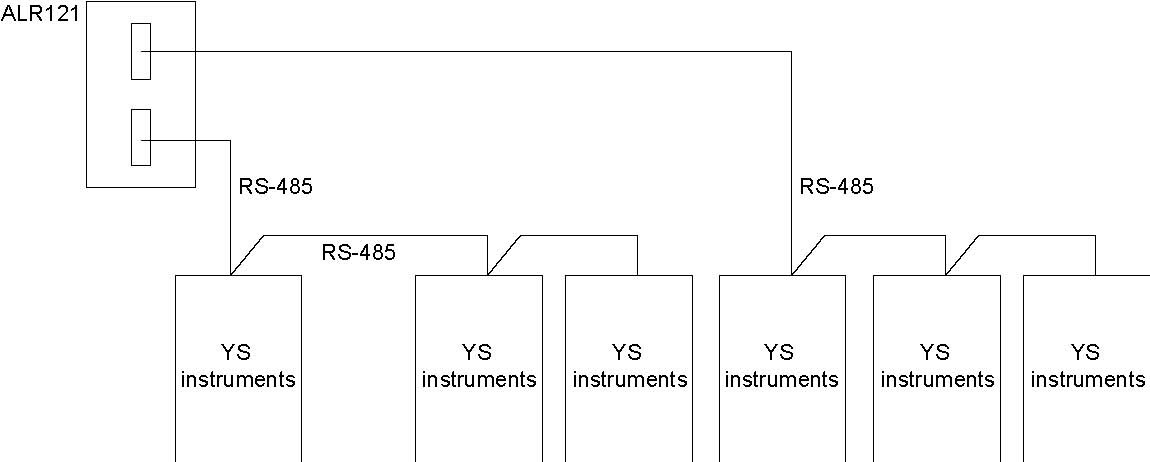
F03E.ai
Figure Hardware Connection Diagram
Table List of Applicable YS Instruments and Data types
|
YS instruments
|
Fast-scan data
|
Slow-scan data (*1)
|
|
YS150/YS1500, YS170/YS1700 Single loop mode or auto-selector mode
|
LS1, PV1, SV1, MV1
|
MH1, ML1, PB1, TI1, TD1
|
|
YS150/YS1500, YS170/YS1700 cascade mode
|
LS1, PV1, SV1, MV1
|
MH1, ML1, PB1, TI1, TD1
|
|
YS170/YS1700 user-programmable mode (BSC1 or SSC)
|
LS1, PV1, SV1, MV1
|
Y04, Y05, Y06, MH1, ML1, PB1, TI1, TD1, P01, P02
|
|
YS170/YS1700 user-programmable mode (CSC)
|
LS1, PV1, SV1, MV1
|
Y04, Y05, Y06, MH1, ML1, PB1, TI1, TD1, P01, P02
|
|
YS135/YS1350
|
LS1, PV1, SV1
|
None
|
|
YS136/YS1360
|
LS1, PV1, MV1
|
MH1, ML1
|
*1: The scan speed of the slow-scan data is described by the fast-scan data speed x n. The figure “n” can be specified within the range of 0-20 by the builder function for each ALR121 port. The default value is set as 0, which is equivalent to x8 of the fast-scan speed.
Table YS Instruments Data and Function Block Data Item
|
YS instruments data
|
Function block data item
|
|
LS1
|
LOOP
|
|
PV1
|
PV
|
|
SV1
|
SV
|
|
MV1
|
MV
|
|
MH1/MH2
|
MH
|
|
ML1/ML2
|
ML
|
|
PB1
|
P
|
|
TI1
|
I
|
|
TD1
|
D
|
|
Y04
|
AUX1
|
|
Y05
|
AUX2
|
|
P01
|
BS
|
|
P02
|
CS
|
No. of connected YS instruments = 20 units (10 units x 2 ports) / ALR121.
modbus
参数资料:
|
ALR111,-ALR121


|
|
|
|
|
 收藏灵猫网
收藏灵猫网