RT-DAC/PCI: Applications
There are two main application areas of the RT-DAC/PCI board. The first one uses the default board configuration. The board can be applied as a part of a measurement and control systems. The available by default inputs and outputs cover the vide range of digital and analog signal processing applications, specially for mechatronic susyems. The available software simplifies access to the RT-DAC/PCI board functions. The board can be controlled by real-time applications (e.g. MATLAB and RTW/RTWT toolboxes), laboratory measurement software (e.g. LabView), industrial monitoring and control packages (SCADA programs e.g. iFIX or InTouch) and even by such applications as MS-Excel.
The RT-DAC/PCI board is equipped with the XILINX FPGA chip. The logic of the FPGA can be reloaded by the user. This feature creates the second application area of the board. The default logic can be replaced by a used designed functions. The reprogramming ability of the RT-DAC/PCI is a unique feature of the board. The reprogramming can be performed unlimited number of times and does not require any hardware changes of the board. As an example the following new RT-DAC/PCI board functions can be implemented:
-
fast, hardware or software triggered, analog or digital signals data acquisition into the internal memory buffers,
-
hardware-implemented analog signal generation,
-
hardware-implemented digital filters of the analog signals,
-
hardware-implemented FFT,
-
and others. Limit is the sky.
It is unique that all the functions of the board can be performed much faster then implemented by other technologies. The data propagation from the input to the output of the board depends only on the logic configuration and typically is equal to 10-20 nanoseconds. It is even 1000 times faster comparing to the microprocessor or DSP systems.
Control of the magnetic levitation system
The magnetic bearing keeps the shaft in the desired central position by levitating in the magnetic field. There are several advantages of such approach. For example, absence of the friction allows higher rotating velocities comparing to the classical bearings. The variable force generated by the magnetic bearing controller can reduce vibrations of the unbalanced rotating parts.
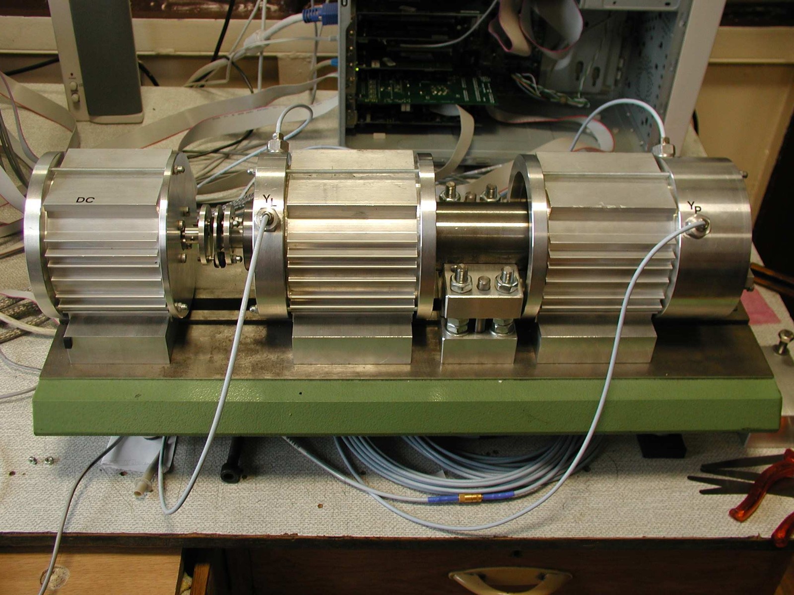
The disadvantage of the magnetic bearing system is the sophisticated magnetic field controller. The satisfactory control results require that the magnetic field control is calculated a few thousand times per second. Presented on the figure the magnetic levitation system consist of two magnetic bearings and a DC drive which drives the shaft. The system requires eight PWM control waves to control the value and orientation of the magnetic field and a single PWM signal to control the DC drive. It is required to measure nine current values, four analog signals proportional to the position of the shaft and the angle of the shaft. The angle of the shaft is measured by the incremental encoder.
The dedicated for the magnetic bearing system logic design supports all the functions required by the magnetic bearing system. The RT-DAC/PCI board can successfully control the system, creating low-cost alternative to dedicated DSP systems.
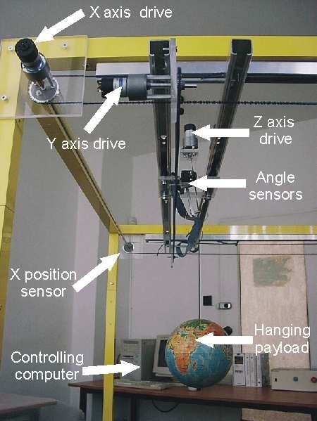
Control of the 3Dcrane system
The laboratory model of the 3D crane presents all aspects of the real gantry crane system. The 3-dimensional movement of the load generates oscillations, which have to be dumped. The controller must drive three drives. There are required position measurements of each axis and two measurements of the angle of the load. The RT-DAC/PCI logic design dedicated for the 3D crane model performs all the required functions. The short response time of the FPGA chip allows the application of the board for the time-critical safety functions. The FPGA hardware detects any exceeding of the 3D crane operating range and immediately cuts off the DC control. Also the FPGA chip sets the control to zero when the temperature of the power amplifier exceeds safety range.
Control of the engine
The modern methods of a fuel engine control require multipoint measurement system. The engine controller changes its parameters depending on the current engine state. The controller measures the engine temperature and the position of the shaft and sets the air-fuel composition. The parameters of the composition are controlled by the accurate timings of the injection impulses. The control of the air-fuel composition requires also the generation of the signals for the inlet and outlet valves. The precise engine control requires that the control signals are generated fast and accurate. The accuracy of the signals can not exceed a couple of microseconds and depends on the shaft position.
The dedicated FPGA logic design for the RT-DAC/PCI board creates efficient laboratory control system for the fuel engine. The parameters of the engine controller can be tuned from MATLAB command window or from real-time Simulink models. The flexibility of MATLAB and Simulink environment allow effective research work.
Control of the model of Anti-lock Breaking System
The Anti-lock Breaking System (ABS) is widely used in modern car construction. The laboratory model of the ABS system allows to study the impulse breaking aspects. The model simulates the road, the car wheel and the break. The continuous or impulse control of breaking can be tested. In the impulse breaking mode the controller must measure velocity of the road, velocity of the wheel and control the breaking force.

The velocities are measured by two incremental encoders. The breaking force is controlled by PWM generator. The process is fast and requires very fast controller response. The dedicated FPGA logic performs all time-critical tasks. The PC computer is a supervisor of the RT-DAC/PCI board and selects the parameters of breaking mode. The computer also acquires real-time data and presents the experimental results.

inteco Sp. z o.o. ul.Lea 203, 30-133 Kraków Poland
Tel./fax: (+48) 12 4304961 Mobile. (+48) 601 536142 E-mail: Inteco@kki.krakow.pl http://www.inteco.cc.pl
RT-DAC – AP1/ENG-Inteco-05/2002
Inteco
 收藏灵猫网
收藏灵猫网