|
加载中,请稍候...
|
|
ps6000pg.en-编程指南
关键词:
ps6000pg.en,编程指南
|
|
|
简介:Introduction Welcome Software licence conditions Trademarks Company details Product information System requirements Installation instructions Programming with the PicoScope 6000 Series Driver System requirements Voltage ranges Triggering Sampling modes Block mode ... |
|
品 牌
|
pico
|

|
|
产 地
|
英国
|
|
型 号
|
PXF3301
|
|
折 扣
|
其他电询
|
|
咨询专家:
|
产品说明:
 
picoScope 6000 Series
PC Oscilloscopes
Programmer s Guide
ps6000pg.en r9 Copyright © 2009-2013 Pico Technology Ltd. All rights reserved.
1 Introduction
1.1 Welcome
The picoScope 6000 Series of oscilloscopes from Pico Technology is a range of compact high-performance units designed to replace traditional bench-top oscilloscopes and digitizers.
This manual explains how to use the Application Programming Interface (API) for the PicoScope 6000 Series scopes. For more information on the hardware, see the PicoScope 6000 Series User s Guide and PicoScope 6000 A/ B/C/D Series User s Guide available separately.
1.2 Software licence conditions
The material contained in this release is licensed, not sold. pico Technology Limited grants a licence to the person who installs this software, subject to the conditions listed below.
Access. The licensee agrees to allow access to this software only to persons who have been informed of these conditions and agree to abide by them.
Usage. The software in this release is for use only with Pico products or with data collected using Pico products.
Copyright. Pico Technology Ltd. claims the copyright of, and retains the rights to, all material (software, documents, etc.) contained in this SDK except the example programs. You may copy and distribute the SDK without restriction, as long as you do not remove any Pico Technology copyright statements. The example programs in the SDK may be modified, copied and distributed for the purpose of developing programs to collect data using Pico products.
Liability. Pico Technology and its agents shall not be liable for any loss, damage or injury, howsoever caused, related to the use of Pico Technology equipment or software, unless excluded by statute.
Fitness for purpose. As no two applications are the same, Pico Technology cannot guarantee that its equipment or software is suitable for a given application. It is your responsibility, therefore, to ensure that the product is suitable for your application.
Mission-critical applications. This software is intended for use on a computer that may be running other software products. For this reason, one of the conditions of the licence is that it excludes use in mission-critical applications, for example life support systems.
Viruses. This software was continuously monitored for viruses during production, but you are responsible for virus-checking the software once it is installed.
Support. If you are dissatisfied with the performance of this software, please contact our technical support staff, who will try to fix the problem within a reasonable time. If you are still dissatisfied, please return the product and software to your supplier within 28 days of purchase for a full refund.
Upgrades. We provide upgrades, free of charge, from our web site at www.Picotech.com. We reserve the right to charge for updates or replacements sent out on physical media.
1.3 Trademarks
Windows, Excel and Visual Basic are registered trademarks or trademarks of Microsoft Corporation in the USA and other countries.
LabVIEW is a registered trademark of National Instruments Corporation.
Pico Technology and PicoScope are trademarks of Pico Technology Limited, registered in the United Kingdom and other countries.
2 Product information
2.1 System requirements
Using with PicoScope for Windows
To ensure that your picoScope 6000 Series PC Oscilloscope operates correctly, you must have a computer with at least the minimum system requirements to run one of the supported operating systems, as shown in the following table. The performance of the oscilloscope will be better with a more powerful PC, and will benefit from a multi-core processor.
Please note the PicoScope software is not installed as part of the SDK.
* While the driver will run on a 64 bit operating system, the driver itself is 32 bit, and therefore will run as 32 bit.
** The oscilloscope will run slowly on a USB 1.1 port. This configuration is not recommended.
Using with custom applications
Drivers are available for Windows XP (SP3 or later), Windows Vista, Windows 7 and Windows 8.
2.2 Installation instructions
IMPORTANT Install the picoScope software before connecting your picoScope 6000 Series oscilloscope to the PC for the first time. This will ensure that Windows correctly recognizes theoscilloscope.
Procedure
-
Follow the instructions in the Installation Guide included with your product package.
-
Connect your oscilloscope to the PC using the USB cable supplied.
Checking the installation
Once you have installed the software and connected the oscilloscope to the PC, start the picoScope software. PicoScope should now display any signal connected to the scope inputs. If a probe is connected to your oscilloscope, you should see a small 50 or 60 hertz signal in the oscilloscope window when you touch the probe tip with your finger.
Moving your PicoScope oscilloscope to another USB port
 Windows XP When you first installed the oscilloscope by plugging it into a USB port, Windows associated the pico driver with that port. If you later move the oscilloscope to a different USB port, Windows will display the New Hardware Found Wizard again. When this occurs, just click Next in the wizard to repeat the installation. If Windows gives a warning about Windows Logo Testing, clickContinue Anyway. As all the software you need is already installed on your computer, there is no need to insert the pico Software CD again. Windows XP When you first installed the oscilloscope by plugging it into a USB port, Windows associated the pico driver with that port. If you later move the oscilloscope to a different USB port, Windows will display the New Hardware Found Wizard again. When this occurs, just click Next in the wizard to repeat the installation. If Windows gives a warning about Windows Logo Testing, clickContinue Anyway. As all the software you need is already installed on your computer, there is no need to insert the pico Software CD again.
Windows Vista/7/8 The process is automatic. When you move the device from one port to another, Windows displays an Installing device driver software message followed by a picoScope 6000 series oscilloscope message. The oscilloscope is then ready for use.
3 Programming with the PicoScope 6000 Series
The ps6000.dll dynamic link library in your PicoScope installation directory allows you to program a picoScope 6000 Series oscilloscope using standard C function calls.
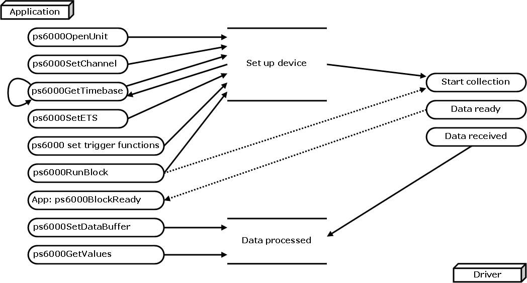
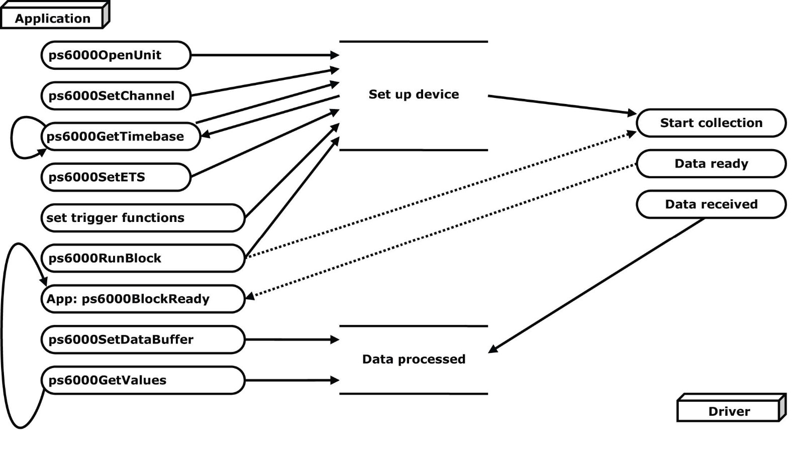
A typical program for capturing data consists of the following steps:
Open the scope unit.
-
Set up the input channels with the required voltage ranges and coupling type .
-
Set up triggering.
-
Start capturing data. (See Sampling modes , where programming is discussed in more detail.)
-
Wait until the scope unit is ready.
-
Stop capturing data.
-
Copy data to a buffer.
-
Close the scope unit.
Numerous sample programs are included in the SDK. These demonstrate how to use the functions of the driver software in each of the modes available.
3.1 Driver
Your application will communicate with a picoScope 6000 API driver called ps6000.dll. The driver exports the PicoScope 6000 function definitions in standard C format, but this does not limit you to programming in C. You can use the API with any programming language that supports standard C calls.
The following low-level drivers are installed by the picoScope 6 software when you plug the picoScope 6000 Series oscilloscope into the computer for the first time. Your application does not call these drivers directly.
USB 2.0
The API driver depends on a kernel driver, Picopp.sys, which works with Windows XP, Windows Vista, Windows 7 and Windows 8. There is a further low-level driver called WinUsb.sys.
USB 3.0
The API driver depends on a kernel driver, cyusb3.sys, which works with Windows XP, Windows Vista, Windows 7. The Windows 8 driver is WinUsb.sys.
3.2 System requirements
General requirements
See System Requirements.
USB
The picoScope 6000 driver offers three different methods of recording data, all of which support USB 1.1, USB 2.0, and USB 3.0. Currently only our C and D models are able to make use of the fastest transfer rates via USB 3.0. For other models, USB 2.0 offers the fastest transfer rates.
3.3 Voltage ranges
You can set a device input channel to any voltage range from ±50 mV to ±20 V with the ps6000SetChannel function. Each sample is scaled to 16 bits so that the values returned to your application are as follows:
Constant
PS6000 MIN VALUE  minimum -32 512 8100 zero 0 0000 PS6000_MAX_VALUE maximum 32 512 7F00 minimum -32 512 8100 zero 0 0000 PS6000_MAX_VALUE maximum 32 512 7F00
3.5 Sampling modes
picoScope 6000 Series oscilloscopes can run in various sampling modes.
-
Block mode
 . In this mode, the scope stores data in internal RAM and then transfers it to the PC. When the data has been collected it is possible to examine the data, with an optional downsampling factor. The data is lost when a new run is started in the same segment , the settings are changed, or the scope is powered down. . In this mode, the scope stores data in internal RAM and then transfers it to the PC. When the data has been collected it is possible to examine the data, with an optional downsampling factor. The data is lost when a new run is started in the same segment , the settings are changed, or the scope is powered down.
-
ETS mode
 . In this mode, it is possible to increase the effective sampling rate of the scope when capturing repetitive signals. It is a modified form of block mode . . In this mode, it is possible to increase the effective sampling rate of the scope when capturing repetitive signals. It is a modified form of block mode .
-
more than one waveform at a time with a minimum of delay between captures. You can use downsampling in this mode if you wish.
-
Streaming mode
 . In this mode, data is passed directly to the PC without being stored in the scope s internal RAM. This enables long periods of slow data collection for chart recorder and data-logging applications. Streaming mode also provides fast streaming at up to 13.33 MS/s (75 ns per sample) with USB 2.0 or 156 MS/s with USB 3.0. Downsampling and triggering are supported in this mode. . In this mode, data is passed directly to the PC without being stored in the scope s internal RAM. This enables long periods of slow data collection for chart recorder and data-logging applications. Streaming mode also provides fast streaming at up to 13.33 MS/s (75 ns per sample) with USB 2.0 or 156 MS/s with USB 3.0. Downsampling and triggering are supported in this mode.
In all sampling modes, the driver returns data asynchronously using a callback . This is a call to one of the functions in your own application. When you request data from the scope, you pass to the driver a pointer to your callback function. When the driver has written the data to your buffer, it makes a callback (calls your function) to signal that the data is ready. The callback function then signals to the application that the data is available.
Because the callback is called asynchronously from the rest of your application, in a separate thread, you must ensure that it does not corrupt any global variables while it runs.
In block mode, you can also poll the driver instead of using a callback.

3.5.1 Block mode
In block mode, the computer prompts a picoScope 6000 series oscilloscope to collect a block of data into its internal memory. When the oscilloscope has collected the whole block, it signals that it is ready and then transfers the whole block to the computer s memory through the USB port.
-
Block size. The maximum number of values depends upon the size of the oscilloscope s memory. The memory buffer is shared between the enabled channels, so if two channels are enabled, each receives half the memory. These features are handled transparently by the driver. The block size also depends on the number of memory segments in use (seeps6000MemorySegments ).
-
Sampling rate. A picoScope 6000 Series oscilloscope can sample at a number of different rates according to the selected timebase and the combination of channels that are enabled. See the picoScope 6000 Series User s Guide for the specifications that apply to your scope model.
-
Setup time. The driver normally performs a number of setup operations, which can take up to 50 milliseconds, before collecting each block of data. If you need to collect data with the minimum time interval between blocks, use rapid block mode and avoid calling setup functions between calls to ps6000RunBlock , ps6000Stop and ps6000GetValues .
Downsampling. When the data has been collected, you can set an optional downsampling factor and examine the data. Downsampling is a process that reduces the amount of data by combining adjacent samples. It is useful for zooming in and out of the data without having to repeatedly transfer the entire contents of the scope s buffer to the PC.
Memory segmentation. The scope s internal memory can be divided into segments so that you can capture several waveforms in succession. Configure this usingps6000MemorySegments.
Data retention. The data is lost when a new run is started in the same segment, the settings are changed, or the scope is powered down.
See Using block mode for programming details.
3.5.1.2 Asynchronous calls in block mode
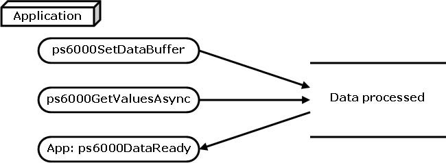
The ps6000GetValues function may take a long time to complete if a large amount of data is being collected. For example, it can take 6 seconds to retrieve the full 1 billion samples from a picoScope 6403 or 6404B. To avoid hanging the calling thread, it is possible to call ps6000GetValuesAsync instead. This immediately returns control to the calling thread, which then has the option of waiting for the data or calling ps6000Stop to abort the operation.
3.5.2 Rapid block mode
In normal block mode, the picoScope 6000 Series scopes collect one waveform at a time. You start the the device running, wait until all samples are collected by the device, and then download the data to the PC or start another run. There is a time overhead of tens of milliseconds associated with starting a run, causing a gap between waveforms. When you collect data from the device, there is another minimum time overhead which is most noticeable when using a small number of samples.
Rapid block mode allows you to sample several waveforms at a time with the minimum time between waveforms. It reduces the gap from milliseconds to less than 1 microsecond.
See Using rapid block mode for details.
3.5.2.1 Using rapid block mode
You can use rapid block mode  with or without aggregation . With aggregation, you need to set up two buffers for each channel to receive the minimum and maximum values. with or without aggregation . With aggregation, you need to set up two buffers for each channel to receive the minimum and maximum values.
3.5.2.2 Rapid block mode example 1: no aggregation
#define MAX_SAMPLES 1000
Set up the device up as usual.
-
Open the device
-
Channels
-
Trigger
-
Number of memory segments (this should be equal or more than the no of captures required)
// set the number of waveforms to 100 ps6000SetNoOfCaptures (handle, 100);
pParameter = false; ps6000RunBlock (
handle,0, // noOfPreTriggerSamples 10000, // noOfPostTriggerSamples 1, // timebase to be used 1, // oversample &timeIndisposedMs,1, // segment index lpReady,&pParameter );
Comment: these variables have been set as an example and can be any valid value. pParameter will be set true by your callback function lpReady.
while (!pParameter) Sleep (0);
for (int i = 0; i < 10; i++)
{ for (int c = PS6000_CHANNEL_A; c <= PS6000_CHANNEL_D; c++){
ps6000SetDataBufferBulk
( handle, c, &buffer[c][i], MAX_SAMPLES, i
); } }
Comments: buffer has been created as a two-dimensional array of pointers to shorts, which will contain 1000 samples as defined by MAX_SAMPLES. There are only 10 buffers set, but it is possible to set up to the number of captures you have requested.
ps6000GetValuesBulk
( handle,&noOfSamples, // set to MAX_SAMPLES on entering the function 10, // fromSegmentIndex 19, // toSegmentIndex 1, // downsampling ratioPS6000_RATIO_MODE_NONE, // downsampling ratio modeoverflow // an array of size 10 shorts
)
Comments: the number of samples could be up to noOfPreTriggerSamples + noOfPostTriggerSamples, the values set in ps6000RunBlock. The samples are always returned from the first sample taken, unlike the ps6000GetValues function which allows the sample index to be set. This function does not support aggregation. The above segments start at 10 and finish at 19 inclusive. It is possible for the fromSegmentIndex to wrap around to the toSegementIndex, by setting the fromSegmentIndex to 98 and the toSegmentIndex to 7.
ps6000GetValuesTriggerTimeOffsetBulk64
( handle, times, timeUnits, 10, 19
)
Comments: the above segments start at 10 and finish at 19 inclusive. It is possible for the fromSegmentIndex to wrap around to the toSegmentIndex, if the fromSegmentIndex is set to 98 and the toSegmentIndex to 7.
3.5.2.3 Rapid block mode example 2: using aggregation
#define MAX_SAMPLES 1000
Set up the device up as usual.
-
Open the device
-
Channels
-
Trigger
-
Number of memory segments (this should be equal or more than the number of captures required)
// set the number of waveforms to 100 ps6000SetNoOfCaptures (handle, 100);
pParameter = false; ps6000RunBlock (
handle, 0, //noOfPreTriggerSamples, 1000000, // noOfPostTriggerSamples, 1, // timebase to be used, 1, // oversample &timeIndisposedMs, 1, // oversample lpReady, &pParameter
);
Comments: the set-up for running the device is exactly the same whether or not aggregation will be used when you retrieve the samples.
for (int c = PS6000_CHANNEL_A; c <= PS6000_CHANNEL_D; c++)
{ ps6000SetDataBuffers (
handle, c, &bufferMax[c], &bufferMin[c] MAX_SAMPLES, PS6000_RATIO_MODE_AGGREGATE
); }
Comments: since only one waveform will be retrieved at a time, you only need to set up one pair of buffers; one for the maximum samples and one for the minimum samples. Again, the buffer sizes are 1000 samples.
for (int segment = 10; segment < 20; segment++)
{ ps6000GetValues (
handle, 0, &noOfSamples, // set to MAX_SAMPLES on entering 1000, &downSampleRatioMode, //set to RATIO_MODE_AGGREGATE index, overflow
);
ps6000GetTriggerTimeOffset64
( handle, &time, &timeUnits, index
) }
Comments: each waveform is retrieved one at a time from the driver with an aggregation of 1000.
3.5.3 ETS (Equivalent Time Sampling)
ETS is a way of increasing the effective sampling rate of the scope when capturing repetitive signals. It is a modified form of block mode, and is controlled by the ps6000SetTrigger andps6000SetEts functions.
Overview. ETS works by capturing several cycles of a repetitive waveform, then combining them to produce a composite waveform that has a higher effective sampling rate than the individual captures. The scope hardware accurately measures the delay, which is a small fraction of a single sampling interval, between each trigger event and the subsequent sample. The driver then shifts each capture slightly in time and overlays them so that the trigger points are exactly lined up. The result is a larger set of samples spaced by a small fraction of the original sampling interval. The maximum effective sampling rates that can be achieved with this method are listed in the User s Guide for the scope device.
Trigger stability. Because of the high sensitivity of ETS mode to small time differences, the trigger must be set up to provide a stable waveform that varies as little as possible from one capture to the next.
Callback. ETS mode returns data to your application using the ps6000BlockReady callback function.
Applicability Available in block mode only. Not suitable for one-shot (non-repetitive) signals. Aggregation and oversampling are not supported. Edge-triggering only. Auto trigger delay(autoTriggerMilliseconds) is ignored.
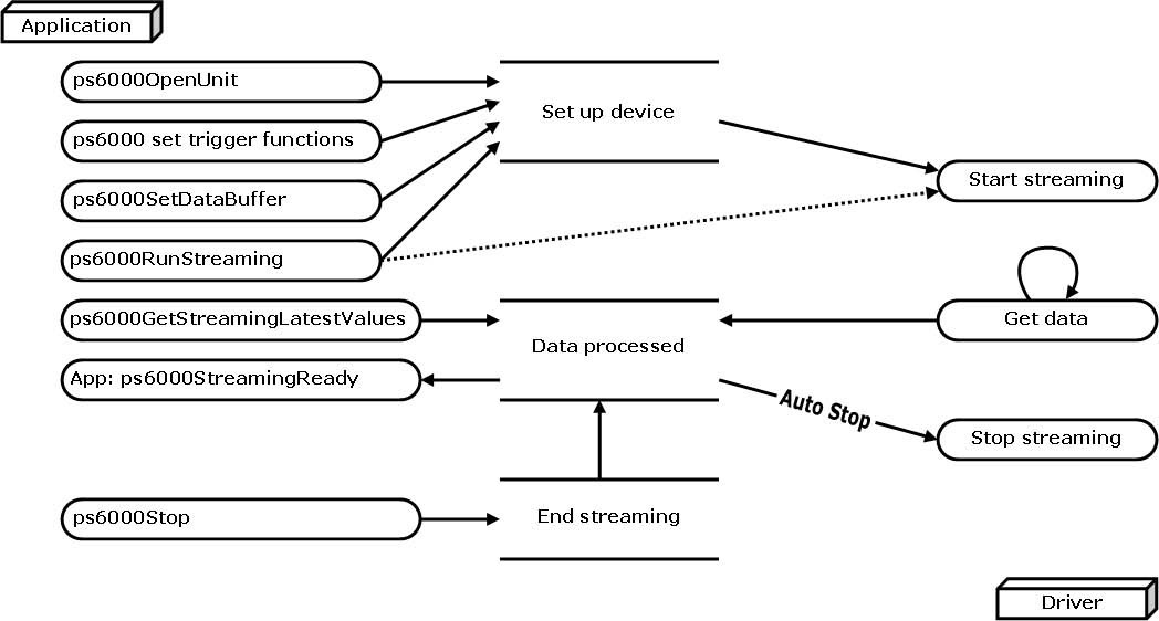
3.5.4 Streaming mode
Streaming mode can capture data without the gaps that occur between blocks when using block mode.
With USB 2.0 it can transfer data to the PC at speeds of at least 13.33 million samples per second (75 nanoseconds per sample), depending on the computer s performance. With USB 3.0 this speed increases to 78 million samples per second (12 nanoseconds per sample). This makes it suitable for high-speed data acquisition, allowing you to capture long data sets limited only by the computer s memory.
Aggregation. The driver returns aggregated readings while the device is streaming. If aggregation is set to 1 then only one buffer is returned per channel. When aggregation is set above 1 then two buffers (maximum and minimum) per channel are returned.
Memory segmentation. The memory can be divided into segments to reduce the latency of data transfers to the PC. However, this increases the risk of losing data if the PC cannot keep up with the device s sampling rate.
See Using streaming mode for programming details.
3.6 Oversampling
Note: This feature is provided for backward-compatibility only. The same effect can be obtained more efficiently with the picoScope 6000 Series using the hardware averaging feature (seeDownsampling modes ).
When the oscilloscope is operating at sampling rates less than its maximum, it is possible to oversample. Oversampling is taking more than one measurement during a time interval and returning the average as one sample. The number of measurements per sample is called the oversampling factor. If the signal contains a small amount of wideband noise (strictly speaking,Gaussian noise), this technique can increase the effective vertical resolution of the oscilloscope by n bits, where n is given approximately by the equation below:
n = log (oversampling factor) / log 4
Conversely, for an improvement in resolution of n bits, the oversampling factor you need is given approximately by:
oversampling factor = 4n
An oversample of 4, for example, would quadruple the time interval and quarter the maximum samples, and at the same time would increase the effective resolution by one bit.
3.7 Timebases
The API allows you to select any of 232 different timebases based on a maximum sampling rate of 5 GHz. The timebases allow slow enough sampling in block mode to overlap the streaming sample intervals, so that you can make a smooth transition between block mode and streaming mode.
3.8 Combining several oscilloscopes
It is possible to collect data using up to 64 picoScope 6000 Series oscilloscopes at the same time, depending on the capabilities of the PC. Each oscilloscope must be connected to a separate USB port. The ps6000OpenUnit function returns a handle to an oscilloscope. All the other functions require this handle for oscilloscope identification. For example, to collect data from two oscilloscopes at the same time:
CALLBACK ps6000BlockReady(...)
// define callback function specific to application
handle1 = ps6000OpenUnit()
handle2 = ps6000OpenUnit()
ps6000SetChannel(handle1) // set up unit 1 ps6000RunBlock(handle1)
ps6000SetChannel(handle2) // set up unit 2 ps6000RunBlock(handle2)
// data will be stored in buffers
// and application will be notified using callback
ready = FALSE
while not ready ready = handle1_ready ready &= handle2_ready
Note: an external clock may be fed into the AUX input to provide some degree of synchronization between multiple oscilloscopes.
3.9 API functions
The picoScope 6000 Series API exports the following functions for you to use in your own applications. All functions are C functions using the standard call naming convention (__stdcall). They are all exported with both decorated and undecorated
names.
ps6000BlockReady indicate when block-mode data ready ps6000CloseUnit close a scope device ps6000DataReady indicate when post-collection data ready ps6000EnumerateUnits find all connected oscilloscopesps6000FlashLed flash the front-panel LED ps6000GetAnalogueOffset get min/max allowable analogue offset ps6000GetMaxDownSampleRatio find out aggregation ratio for data ps6000GetStreamingLatestValuesget streaming data while scope is running ps6000GetTimebase find out what timebases are available ps6000GetTimebase2 find out what timebases are available ps6000GetTriggerTimeOffset find out when trigger occurred (32-bit) ps6000GetTriggerTimeOffset64 find out when trigger occurred (64-bit) ps6000GetUnitInfo read information about scope device ps6000GetValues get block-mode data with callbackps6000GetValuesAsync get streaming data with callback ps6000GetValuesBulk get data in rapid block mode ps6000GetValuesBulkAsync get data in rapid block mode using callback ps6000GetValuesOverlappedset up data collection ahead of capture ps6000GetValuesOverlappedBulk set up data collection in rapid block mode ps6000GetValuesTriggerTimeOffsetBulk get rapid-block waveform timings (32-bit)ps6000GetValuesTriggerTimeOffsetBulk64 get rapid-block waveform timings (64-bit) ps6000IsReady poll driver in block mode ps6000IsTriggerOrPulseWidthQualifierEnabled find out whether trigger is enabledps6000MemorySegments divide scope memory into segments ps6000NoOfStreamingValues get number of samples in streaming mode ps6000OpenUnit open a scope device ps6000OpenUnitAsync open a scope device without waiting ps6000OpenUnitProgress check progress of OpenUnit call ps6000RunBlock start block mode ps6000RunStreaming start streaming mode ps6000SetChannel set up input channelsps6000SetDataBuffer register data buffer with driver ps6000SetDataBufferBulk set the buffers for each waveform ps6000SetDataBuffers register aggregated data buffers with driver ps6000SetDataBuffersBulkregister data buffers for rapid block mode ps6000SetEts set up equivalent-time sampling ps6000SetEtsTimeBuffer set up buffer for ETS timings (64-bit) ps6000SetEtsTimeBuffers set up buffer for ETS timings (32-bit) ps6000SetExternalClock set AUX input to receive external clock ps6000SetNoOfCaptures set number of captures to collect in one run ps6000SetPulseWidthQualifier set up pulse width triggeringps6000SetSigGenArbitrary set up arbitrary waveform generator ps6000SetSigGenBuiltIn set up standard signal generator ps6000SetSimpleTrigger set up level triggers only ps6000SetTriggerChannelConditionsspecify which channels to trigger on ps6000SetTriggerChannelDirections set up signal polarities for triggering ps6000SetTriggerChannelProperties set up trigger thresholds ps6000SetTriggerDelay set up post-trigger delay ps6000SigGenSoftwareControl trigger the signal generator ps6000Stop stop data capture ps6000StreamingReady indicate when streaming-mode data ready
3.9.1 ps6000BlockReady
typedef void (CALLBACK *ps6000BlockReady)
( short handle, pico_STATUS status, void * pParameter
)
This callback function is part of your application. You register it with the picoScope 6000 series driver using ps6000RunBlock, and the driver calls it back when block-mode data is ready. You can then download the data using the ps6000GetValues function.
3.9.2 ps6000CloseUnit
pico_STATUS ps6000CloseUnit( short handle )
This function shuts down a PicoScope 6000 oscilloscope.
3.9.3 ps6000DataReady
typedef void (CALLBACK *ps6000DataReady)
( short handle, Pico_STATUS status, unsigned long noOfSamples, short overflow, void * pParameter
)
This is a callback function that you write to collect data from the driver. You supply a pointer to the function when you call ps6000GetValuesAsync , and the driver calls your function back when the data is ready.
3.9.4 ps6000EnumerateUnits
pico_STATUS ps6000EnumerateUnits
( short * count, char * serials, short * serialLth
)
This function counts the number of PicoScope 6000 units connected to the computer, and returns a list of serial numbers as a string.
|
Applicability
|
All modes
|
|
Arguments
|
* count, on exit, the number of PicoScope 6000 units found * serials, on exit, a list of serial numbers separated by commas and terminated by a final null. Example:AQ005/139,VDR61/356,ZOR14/107. Can be NULL on entry if serial numbers are not required. * serialLth, on entry, the length of the char buffer pointed to by serials; on exit, the length of the string written to serials
|
|
Returns
|
pico_OK Pico_BUSY Pico_NULL_PARAMETER Pico_FW_FAIL Pico_CONFIG_FAIL Pico_MEMORY_FAIL Pico_ANALOG_BOARD Pico_CONFIG_FAIL_AWG Pico_INITIALISE_FPGA
|
3.9.5 ps6000FlashLed
Pico_STATUS ps6000FlashLed
( short handle, short start
)
This function flashes the LED on the front of the scope without blocking the calling thread. Calls to ps6000RunStreaming and ps6000RunBlock cancel any flashing started by this function. It is not possible to set the LED to be constantly illuminated, as this state is used to indicate that the scope has not been initialized.
|
Applicability
|
All modes
|
|
Arguments
|
handle, the handle of the scope device
|
|
|
start, the action required:
|
|
|
< 0 : flash the LED indefinitely. 0 : stop the LED flashing. > 0 : flash the LED start times. If the LED is already flashing on entry to this function, the flash count will be reset to start.
|
|
Returns
|
pico_OK Pico_HANDLE_INVALID
|
|
|
Pico_BUSY
|
|
|
Pico_DRIVER_FUNCTION
|
|
|
Pico_NOT_RESPONDING
|
3.9.6 ps6000GetAnalogueOffset
Pico_STATUS ps6000GetAnalogueOffset
( short handle, PS6000_RANGE, range PS6000_COUPLING coupling float * maximumVoltage, float * minimumVoltage
)
This function is used to get the maximum and minimum allowable analog offset for a specific voltage range.
|
Applicability
|
Not PicoScope 6407
|
|
Arguments
|
handle, the value returned from opening the device. range, the voltage range to be used when gathering the min and max information. coupling, the type of AC/DC coupling used. * maximumVoltage, a pointer to a float, an out parameter set to the maximum voltage allowed for the range, may be NULL. * minimumVoltage, a pointer to a float, an out parameter set to the minimum voltage allowed for the range, may be NULL. If bothmaximumVoltageand minimumVoltageare set to NULLthe driver will return Pico NULL PARAMETER.
|
|
Returns
|
pico_OK Pico_INVALID_HANDLE Pico_DRIVER_FUNCTION Pico_INVALID_VOLTAGE_RANGE Pico_NULL_PARAMETER
|
3.9.7 ps6000GetMaxDownSampleRatio
Pico_STATUS ps6000GetMaxDownSampleRatio
( short handle, unsigned long noOfUnaggregatedSamples, unsigned long * maxDownSampleRatio, PS6000_RATIO_MODE downSampleRatioMode, unsigned long segmentIndex
)
This function returns the maximum downsampling ratio that can be used for a given number of samples in a given downsampling mode.
3.9.8 ps6000GetNoOfCaptures
Pico_STATUS ps6000GetNoOfCaptures
( short handle, unsigned long * nCaptures
)
This function finds out how many captures are available after ps6000RunBlock has been called when either the collection completed or the collection of waveforms was interrupted by calling ps6000Stop . The returned value (nCaptures) can then be used to iterate through the number of segments using ps6000GetValues , or in a single call tops6000GetValuesBulk where it is used to calculate the toSegmentIndex parameter.
3.9.9 ps6000GetStreamingLatestValues
Pico_STATUS ps6000GetStreamingLatestValues
( short handle, ps6000StreamingReady lpPs6000Ready, void * pParameter
)
This function instructs the driver to return the next block of values to your ps6000StreamingReady callback function. You must have previously called ps6000RunStreaming beforehand to set up streaming.
3.9.10 ps6000GetTimebase
Pico_STATUS ps6000GetTimebase
( short handle, unsigned long timebase, unsigned long noSamples, long * timeIntervalNanoseconds, short oversample, unsigned long * maxSamples unsigned long segmentIndex
)
This function calculates the sampling rate and maximum number of samples for a given timebase under the specified conditions. The result will depend on the number of channels enabled by the last call to ps6000SetChannel.
This function is provided for use with programming languages that do not support the float data type. The value returned in the timeIntervalNanoseconds argument is restricted to integers. If your programming language supports the float type, then we recommend that you use ps6000GetTimebase2 instead.
To use ps6000GetTimebase or ps6000GetTimebase2, first estimate the timebase number that you require using the information in the timebase guide. Pass this timebase to the GetTimebase function and check the returned timeIntervalNanoseconds argument. If necessary, repeat until you obtain the time interval that you need.
|
Applicability
|
All modes
|
|
Arguments
|
handle, the handle of the required device. timebase, see timebase guide noSamples, the number of samples required. This value is used to calculate the most suitable time unit to use.timeIntervalNanoseconds, on exit, the time interval between readings at the selected timebase. Use NULL if not required.oversample, the amount of oversample required. Range: 0 toPS6000_MAX_OVERSAMPLE_8BIT. maxSamples, on exit, the maximum number of samples available. The result may vary depending on the number of channels enabled, the timebase chosen and the oversample selected. Use NULL if not required.segmentIndex, the index of the memory segment to use.
|
|
Returns
|
pico_OK Pico_INVALID_HANDLE Pico_TOO_MANY_SAMPLES Pico_INVALID_CHANNEL Pico_INVALID_TIMEBASE Pico_INVALID_PARAMETER Pico_SEGMENT_OUT_OF_RANGE Pico_DRIVER_FUNCTION
|
3.9.11 ps6000GetTimebase2
Pico_STATUS ps6000GetTimebase2
( short handle,
unsigned long timebase,
unsigned long noSamples,
float * timeIntervalNanoseconds,
short oversample,
unsigned long * maxSamples
unsigned long segmentIndex )
This function is an upgraded version of ps6000GetTimebase , and returns the time interval as a float rather than a long. This allows it to return sub-nanosecond time intervals. Seeps6000GetTimebase for a full description.
3.9.12 ps6000GetTriggerTimeOffset
pico_STATUS ps6000GetTriggerTimeOffset
( short handle unsigned long * timeUpper unsigned long * timeLower PS6000_TIME_UNITS * timeUnits unsigned long segmentIndex
)
This function gets the time, as two 4-byte values, at which the trigger occurred. Call it after block-mode data has been captured or when data has been retrieved from a previous block-mode capture. A 64-bit version of this function, ps6000GetTriggerTimeOffset64 , is also available.
3.9.13 ps6000GetTriggerTimeOffset64
Pico_STATUS ps6000GetTriggerTimeOffset64
( short handle, __int64 * time, PS6000_TIME_UNITS * timeUnits, unsigned long segmentIndex
)
This function gets the time, as a single 64-bit value, at which the trigger occurred. Call it after block-mode data has been captured or when data has been retrieved from a previous block-mode capture. A 32-bit version of this function, ps6000GetTriggerTimeOffset, is also available.
3.9.14 ps6000GetUnitInfo
Pico_STATUS ps6000GetUnitInfo
( short handle, char * string, short stringLength, short * requiredSize Pico_INFO info
)
This function retrieves information about the specified oscilloscope. If the device fails to open, only the driver version and error code are available to explain why the last open unit call failed.
|
Applicability
|
All modes
|
|
Arguments
|
handle, the handle of the device from which information is required. If an invalid handle is passed, the error code from the last unit that failed to open is returned. string, on exit, the unit information string selected specified by the info argument. Ifstring is NULL, only requiredSize is returned.stringLength, the maximum number of chars that may be written to string. requiredSize, on exit, the required length of the string array. info, a number specifying what information is required. The possible values are listed in the table below.
|
|
Returns
|
pico_OK Pico_INVALID_HANDLE Pico_NULL_PARAMETER Pico_INVALID_INFO Pico_INFO_UNAVAILABLE Pico_DRIVER_FUNCTION
|
|
info Example 0 Pico_DRIVER_VERSION -Version number of PicoScope 6000 DLL1,0,0,1 1 Pico_USB_VERSION -Type of USB connection to device: 1.1, 2.0 or 3.03.0 2 Pico HARDWARE VERSION -Hardware version of device 1 3 Pico VARIANT INFO -Model number of device 6403 4 Pico BATCH AND SERIAL -Batch and serial number of device KJL87/6 5 Pico CAL DATE -Calibration date of device 30Sep096 Pico KERNEL VERSION -Version of kernel driver 1,1,2,4 7Pico_DIGITAL_HARDWARE_VERSION -Hardware version of the digital section 1 8Pico_ANALOGUE_HARDWARE_VERSION -Hardware version of the analogue section 19 Pico_FIRMWARE_VERSION_1 -Version information of Firmware 1 1,0,0,1 APico_FIRMWARE_VERSION_2 -Version information of Firmware 2 1,0,0,1
|
3.9.15 ps6000GetValues
Pico_STATUS ps6000GetValues
( short handle, unsigned long startIndex, unsigned long * noOfSamples, unsigned long downSampleRatio, PS6000_RATIO_MODE downSampleRatioMode, unsigned long segmentIndex, short * overflow
)
This function returns block-mode data, with or without downsampling , starting at the specified sample number. It is used to get the stored data from the driver after data collection has stopped.
Applicability Block mode , rapid block mode
Arguments handle, the handle of the required device.
startIndex, a zero-based index that indicates the start point for data collection. It is measured in sample intervals from the start of the buffer.
noOfSamples, on entry, the number of samples required. On exit, the actual number retrieved. The number of samples retrieved will not be more than the number requested, and the data retrieved always starts with the first sample captured.
downSampleRatio, the downsampling factor that will be applied to the raw data.
downSampleRatioMode, which downsampling mode to use. The
available values are: PS6000_RATIO_MODE_NONE (downSampleRatio is ignored) PS6000_RATIO_MODE_AGGREGATE PS6000_RATIO_MODE_AVERAGEPS6000_RATIO_MODE_DECIMATE
AGGREGATE, AVERAGE, and DECIMATE are single-bit constants that can be ORed to apply multiple downsampling modes to the same data. DISTRIBUTION mode is not implemented.
segmentIndex, the zero-based number of the memory segment where the data is stored.
overflow, on exit, a set of flags that indicate whether an overvoltage has occurred on any of the channels. It is a bit field with bit 0 denoting Channel A.
Returns pico_OK Pico_INVALID_HANDLE Pico_NO_SAMPLES_AVAILABLE Pico_DEVICE_SAMPLING Pico_NULL_PARAMETER Pico_SEGMENT_OUT_OF_RANGE Pico_INVALID_PARAMETER Pico_TOO_MANY_SAMPLES Pico_DATA_NOT_AVAILABLE Pico_STARTINDEX_INVALID Pico_INVALID_SAMPLERATIO Pico_INVALID_CALL Pico_NOT_RESPONDING Pico_MEMORY Pico_RATIO_MODE_NOT_SUPPORTED Pico_DRIVER_FUNCTION
3.9.15.1 Downsampling modes
Various methods of data reduction, or downsampling, are possible with the PicoScope 6000 Series oscilloscopes. The downsampling is done at high speed by dedicated hardware inside the scope, making your application faster and more responsive than if you had to do all the data processing in software.
You specify the downsampling mode when you call one of the data collection functions such as ps6000GetValues. The following modes are available:
PS6000_RATIO_MODE_AGGREGATE Reduces every block of n values to just two values: a minimum and a maximum. The minimum and maximum values are returned in two separate buffers.
PS6000_RATIO_MODE_AVERAGE Reduces every block of n values to a single value representing the average (arithmetic mean) of all the values.
PS6000_RATIO_MODE_DECIMATE Reduces every block of n values to just the first value in the block, discarding all the other values.
Not implemented.
PS6000_RATIO_MODE_DISTRIBUTION
3.9.16 ps6000GetValuesAsync
pico_STATUS ps6000GetValuesAsync
( short handle, unsigned long startIndex, unsigned long noOfSamples, unsigned long downSampleRatio, PS6000_RATIO_MODE downSampleRatioMode,unsigned long segmentIndex, void * lpDataReady, void * pParameter
)
This function returns data either with or without downsampling , starting at the specified sample number. It is used to get the stored data from the scope after data collection has stopped. It returns the data using a callback .
3.9.17 ps6000GetValuesBulk
Pico_STATUS ps6000GetValuesBulk
( short handle, unsigned long * noOfSamples, unsigned long fromSegmentIndex, unsigned long toSegmentIndex, unsigned long downSampleRatio,PS6000_RATIO_MODE downSampleRatioMode, short * overflow
)
This function retrieves waveforms captured using rapid block mode. The waveforms must have been collected sequentially and in the same run. This method of collection does not supportdownsampling.
3.9.18 ps6000GetValuesBulkAsync
Pico_STATUS ps6000GetValuesBulkAsync
( short handle, unsigned long startIndex, unsigned long * noOfSamples, unsigned long downSampleRatio, PS6000_RATIO_MODE downSampleRatioMode, unsigned long fromSegmentIndex, unsigned long toSegmentIndex, short * overflow
)
This function retrieves more than one waveform at a time in rapid block mode after data collection has stopped. The waveforms must have been collected sequentially and in the same run. The data is returned using a callback .
3.9.19 ps6000GetValuesOverlapped
Pico_STATUS ps6000GetValuesOverlapped
( short handle, unsigned long startIndex, unsigned long * noOfSamples, unsigned long downSampleRatio, PS6000_RATIO_MODE downSampleRatioMode,unsigned long segmentIndex, short * overflow
)
This function allows you to make a deferred data-collection request, which will later be executed, and the arguments validated, when you call ps6000RunBlock in block mode. The advantage of this function is that the driver makes contact with the scope only once, when you call ps6000RunBlock , compared with the two contacts that occur when you use the conventional ps6000RunBlock ,ps6000GetValues calling sequence. This slightly reduces the dead time between successive captures in block mode.
After calling ps6000RunBlock , you can optionally use ps6000GetValues to request further copies of the data. This might be required if you wish to display the data with different data reduction settings.
3.9.20 ps6000GetValuesOverlappedBulk
Pico_STATUS ps6000GetValuesOverlappedBulk
( short handle,
unsigned long startIndex,
unsigned long * noOfSamples,
unsigned long downSampleRatio,
PS6000_RATIO_MODE downSampleRatioMode,
unsigned long fromSegmentIndex,
unsigned long toSegmentIndex,
short * overflow
)
This function allows you to make a deferred data-collection request, which will later be executed, and the arguments validated, when you call ps6000RunBlock in rapid block mode. The advantage of this method is that the driver makes contact with the scope only once, when you call ps6000RunBlock , compared with the two contacts that occur when you use the conventional ps6000RunBlock, ps6000GetValues calling sequence. This slightly reduces the dead time between successive captures in rapid block mode.
After calling ps6000RunBlock , you can optionally use ps6000GetValues to request further copies of the data. This might be required if you wish to display the data with different data reduction settings.
3.9.21 ps6000GetValuesTriggerTimeOffsetBulk
Pico_STATUS ps6000GetValuesTriggerTimeOffsetBulk
( short handle, unsigned long * timesUpper, unsigned long * timesLower, PS6000_TIME_UNITS * timeUnits, unsigned long fromSegmentIndex,unsigned long toSegmentIndex
)
This function retrieves the time offsets, as lower and upper 32-bit values, for waveforms obtained in rapid block mode .
This function is provided for use in programming environments that do not support 64-bit integers. If your programming environment supports this data type, it is easier to useps6000GetValuesTriggerTimeOffsetBulk64.
|
Applicability
|
Rapid block mode
|
|
Arguments
|
handle, the handle of the device * timesUpper, an array of integers. On exit, the most significant 32 bits of the time offset for each requested segment index. times [0] will hold thefromSegmentIndex time offset and the last times index will hold the toSegmentIndex time offset. The array must be long enough to hold the number of requested times. * timesLower, an array of integers. On exit, the least-significant 32 bits of the time offset for each requested segment index. times [0] will hold thefromSegmentIndex time offset and the last times index will hold the toSegmentIndex time offset. The array size must be long enough to hold the number of requested times. * timeUnits, an array of integers. The array must be long enough to hold the number of requested times. On exit, timeUnits[0] will contain the time unit for fromSegmentIndex and the last element will contain the time unit for toSegmentIndex. fromSegmentIndex, the first segment for which the time offset is required toSegmentIndex,the last segment for which the time offset is required. IftoSegmentIndex is less than fromSegmentIndex then the driver will wrap around from the last segment to the first.
|
|
Returns
|
pico_OK Pico_INVALID_HANDLE Pico_NULL_PARAMETER Pico_DEVICE_SAMPLING Pico_SEGMENT_OUT_OF_RANGE Pico_NO_SAMPLES_AVAILABLE Pico_DRIVER_FUNCTION
|
3.9.22 ps6000GetValuesTriggerTimeOffsetBulk64
Pico_STATUS ps6000GetValuesTriggerTimeOffsetBulk64
( short handle, __int64 * times, PS6000_TIME_UNITS * timeUnits, unsigned long fromSegmentIndex, unsigned long toSegmentIndex
)
This function retrieves the 64-bit time offsets for waveforms captured in rapid block mode.
A 32-bit version of this function, ps6000GetValuesTriggerTimeOffsetBulk , is available for use with programming languages that do not support 64-bit integers.
|
Applicability
|
Rapid block mode
|
|
Arguments
|
handle, the handle of the device * times, an array of integers. On exit, this will hold the time offset for each requested segment index. times[0] will hold the time offset for fromSegmentIndex,and the last times index will hold the time offset fortoSegmentIndex. The array must be long enough to hold the number of times requested. * timeUnits, an array of integers long enough to hold the number of requested times. timeUnits[0]will contain the time unit for fromSegmentIndex, and the last element will contain the toSegmentIndex. fromSegmentIndex,the first segment for which the time offset is required. The results for this segment will be placed in times[0] and timeUnits[0].toSegmentIndex, the last segment for which the time offset is required. The results for this segment will be placed in the last elements of the times and timeUnits arrays. IftoSegmentIndex is less than fromSegmentIndex then the driver will wrap around from the last segment to the first.
|
|
Returns
|
pico_OK Pico_INVALID_HANDLE Pico_NULL_PARAMETER Pico_DEVICE_SAMPLING Pico_SEGMENT_OUT_OF_RANGE Pico_NO_SAMPLES_AVAILABLE Pico_DRIVER_FUNCTION
|
3.9.23 ps6000IsReady
Pico_STATUS ps6000IsReady
( short handle, short * ready
)
This function may be used instead of a callback function to receive data from ps6000RunBlock . To use this method, pass a NULL pointer as the lpReady argument tops6000RunBlock . You must then poll the driver to see if it has finished collecting the requested samples.
3.9.24 ps6000IsTriggerOrPulseWidthQualifierEnabled
pico_STATUS ps6000IsTriggerOrPulseWidthQualifierEnabled
(
short handle,
short * triggerEnabled,
short * pulseWidthQualifierEnabled
)
This function discovers whether a trigger, or pulse width triggering, is enabled.
3.9.25 ps6000MemorySegments
Pico_STATUS ps6000MemorySegments
( short handle unsigned long nSegments, unsigned long * nMaxSamples
)
This function sets the number of memory segments that the scope will use.
When the scope is opened, the number of segments defaults to 1, meaning that each capture fills the scope s available memory. This function allows you to divide the memory into a number of segments so that the scope can store several waveforms sequentially.
|
Applicability
|
All modes
|
|
Arguments
|
handle, the handle of the required device nSegments, the number of segments required: Model Number Min Max 6402 1 32 768 6402A 1 125 000 6402B 1 250 000 6402C 1 250 000 6402D 1500 000 6403 1 1 000 000 6403A 1 250 000 6403B 1 500 000 6403C1 500 000 6403D 1 1 000 000 6404 1 1 000 000 6404A 1 500 0006404B 1 1 000 000 6404C 1 1 000 000 6404D 1 2 000 000 6407 1 1 000 000 * nMaxSamples, on exit, the number of samples available in each segment. This is the total number over all channels, so if more than one channel is in use then the number of samples available to each channel is nMaxSamples divided by the number of channels.
|
|
Returns
|
pico_OK Pico_USER_CALLBACK Pico_INVALID_HANDLE Pico_TOO_MANY_SEGMENTS Pico_MEMORY Pico_DRIVER_FUNCTION
|
3.9.26 ps6000NoOfStreamingValues
Pico_STATUS ps6000NoOfStreamingValues
( short handle, unsigned long * noOfValues
)
This function returns the number of samples available after data collection in streaming mode. Call it after calling ps6000Stop .
|
Applicability
|
Streaming mode
|
|
Arguments
|
handle, the handle of the required device
|
|
|
* noOfValues, on exit, the number of samples
|
|
Returns
|
pico_OK Pico_INVALID_HANDLE Pico_NULL_PARAMETER Pico_NO_SAMPLES_AVAILABLE Pico_NOT_USED Pico_BUSY Pico_DRIVER_FUNCTION
|
3.9.27 ps6000OpenUnit
Pico_STATUS ps6000OpenUnit
( short * handle, char * serial
)
This function opens a PicoScope 6000 Series scope attached to the computer. The maximum number of units that can be opened depends on the operating system, the kernel driver and the computer.
|
Applicability
|
All modes
|
|
Arguments
|
* handle, on exit, the result of the attempt to open a scope: -1 : if the scope fails to open 0 : if no scope is found > 0 : a number that uniquely identifies the scope If a valid handle is returned, it must be used in all subsequent calls to API functions to identify this scope. serial, on entry, a null-terminated string containing the serial number of the scope to be opened. If serial is NULL then the function opens the first scope found; otherwise, it tries to open the scope that matches the string.
|
|
Returns
|
pico_OK Pico_OS_NOT_SUPPORTED Pico_OPEN_OPERATION_IN_PROGRESS Pico_EEPROM_CORRUPT Pico_KERNEL_DRIVER_TOO_OLD Pico_FW_FAIL Pico_MAX_UNITS_OPENED Pico_NOT_FOUND (if the specified unit was not found) Pico_NOT_RESPONDING Pico_MEMORY_FAIL Pico_ANALOG_BOARD Pico_CONFIG_FAIL_AWG Pico_INITIALISE_FPGA
|
3.9.28 ps6000OpenUnitAsync
Pico_STATUS ps6000OpenUnitAsync
( short * status char * serial
)
This function opens a scope without blocking the calling thread. You can find out when it has finished by periodically calling ps6000OpenUnitProgress until that function returns a non-zero value.
|
Applicability
|
All modes
|
|
Arguments
|
* status, a status code: 0 if the open operation was disallowed because another open operation is in progress 1 if the open operation was successfully started
|
|
|
* serial: see ps6000OpenUnit
|
|
Returns
|
pico_OK Pico_OPEN_OPERATION_IN_PROGRESS Pico_OPERATION_FAILED
|
3.9.29 ps6000OpenUnitProgress
Pico_STATUS ps6000OpenUnitProgress
( short * handle, short * progressPercent, short * complete
)
This function checks on the progress of a request made to ps6000OpenUnitAsync to open a scope.
3.9.30 ps6000RunBlock
Pico_STATUS ps6000RunBlock
( short handle, unsigned long noOfPreTriggerSamples, unsigned long noOfPostTriggerSamples, unsigned long timebase, short oversample, long * timeIndisposedMs, unsigned long segmentIndex, ps6000BlockReady lpReady, void * pParameter
)
This function starts collecting data in block mode. For a step-by-step guide to this process, see Using block mode .
The number of samples is determined by noOfPreTriggerSamples and noOfPostTriggerSamples (see below for details). The total number of samples must not be more than the size of the segment referred to by segmentIndex.
|
Applicability
|
Block mode, rapid block mode
|
|
Arguments
|
handle, the handle of the required device.noOfPreTriggerSamples, the number of samples to return before the trigger event. If no trigger has been set then this argument is ignored and noOfPostTriggerSamples specifies the maximum number of samples to collect.noOfPostTriggerSamples, the number of samples to be taken after a trigger event. If no trigger event has been set then this specifies the maximum number of samples to be taken. If a trigger condition has been set, this specifies the number of samples to be taken after a trigger has fired, and the number of samples to be collected is then: noOfPreTriggerSamples + noOfPostTriggerSamples timebase, a number in the range 0 to 232-1. See the guide to calculating timebase values.oversample, the oversampling factor, a number in the range 1 to 256. * timeIndisposedMs, on exit, the time, in milliseconds, that the scope will spend collecting samples. This does not include any auto trigger timeout. If this pointer is null, nothing will be written here. segmentIndex, zero-based, specifies which memory segment to use. lpReady, a pointer to the ps6000BlockReadycallback function that the driver will call when the data has been collected. To use the ps6000IsReady polling method instead of a callback function, set this pointer to NULL.
|
* pParameter, a void pointer that is passed to the ps6000BlockReady callback function. The callback can use this pointer to return arbitrary data to the application.
Returns pico_OK Pico_INVALID_HANDLE Pico_USER_CALLBACK Pico_SEGMENT_OUT_OF_RANGE Pico_INVALID_CHANNEL Pico_INVALID_TRIGGER_CHANNEL Pico_INVALID_CONDITION_CHANNEL Pico_TOO_MANY_SAMPLES Pico_INVALID_TIMEBASE Pico_NOT_RESPONDING Pico_CONFIG_FAIL Pico_INVALID_PARAMETER Pico_NOT_RESPONDING Pico_TRIGGER_ERROR Pico_DRIVER_FUNCTION Pico_EXTERNAL_FREQUENCY_INVALIDPico_FW_FAIL Pico_NOT_ENOUGH_SEGMENTS (in Bulk mode) Pico_TRIGGER_AND_EXTERNAL_CLOCK_CLASH Pico_PWQ_AND_EXTERNAL_CLOCK_CLASHPico_PULSE_WIDTH_QUALIFIERPico_SEGMENT_OUT_OF_RANGE (in Overlapped mode) Pico_STARTINDEX_INVALID (in Overlapped mode) Pico_INVALID_SAMPLERATIO (in Overlapped mode) Pico_CONFIG_FAIL
3.9.31 ps6000RunStreaming
Pico_STATUS ps6000RunStreaming
( short handle, unsigned long * sampleInterval, PS6000_TIME_UNITS sampleIntervalTimeUnits unsigned long maxPreTriggerSamples, unsigned long maxPostTriggerSamples, short autoStop, unsigned long downSampleRatio, PS6000_RATIO_MODE downSampleRatioMode, unsigned long overviewBufferSize
)
This function tells the oscilloscope to start collecting data in streaming mode . When data has been collected from the device it is downsampled if necessary and then delivered to the application. Call ps6000GetStreamingLatestValues to retrieve the data. See Using streaming mode for a step-by-step guide to this process.
When a trigger is set, the total number of samples stored in the driver is the sum of maxPreTriggerSamples and maxPostTriggerSamples. If autoStop is false then this will become the maximum number of samples without downsampling.
Applicability Streaming mode
Arguments handle, the handle of the required device.
* sampleInterval, on entry, the requested time interval between samples; on exit, the actual time interval used.
sampleIntervalTimeUnits, the unit of time used for sampleInterval. Use one of these values:
PS6000_FS PS6000_PS PS6000_NS PS6000_US PS6000_MS PS6000_S
maxPreTriggerSamples, the maximum number of raw samples before a trigger event for each enabled channel. If no trigger condition is set this argument is ignored.
maxPostTriggerSamples, the maximum number of raw samples after a trigger event for each enabled channel. If no trigger condition is set, this argument states the maximum number of samples to be stored.
autoStop, a flag that specifies if the streaming should stop when all of maxSamples have been captured.
downSampleRatio: see ps6000GetValues downSampleRatioMode: see ps6000GetValues
3.9.32 ps6000SetChannel
Pico_STATUS ps6000SetChannel
( short handle, PS6000_CHANNEL channel, short enabled, PS6000_COUPLING type, PS6000_RANGE range, float analogueOffset,PS6000_BANDWIDTH_LIMITER bandwidth
)
This function specifies whether an input channel is to be enabled, its input coupling type, voltage range, analog offset and bandwidth limit. Some of the arguments within this function have model-specific values. Please consult the relevant section below according to the model you have.
|
Applicability
|
All modes
|
|
Arguments
|
handle, the handle of the required device channel, the channel to be configured. The values are: PS6000_CHANNEL_A: Channel input PS6000_CHANNEL_B: Channel input PS6000_CHANNEL_C:Channel input PS6000_CHANNEL_D: Channel input enabled,whether or not to enable the channel. The values are: TRUE:enable FALSE: do not enable type, the impedance and coupling type. The values supported are: picoScope 6402/6403/6404 (all model variants) PS6000_AC, 1 megohm impedance, AC coupling. The channel accepts input frequencies from about 1 hertz up to its maximum -3 dB analog bandwidth. PS6000_DC_1M, 1 megohm impedance, DC coupling. The scope accepts all input frequencies from zero (DC) up to its maximum -3 dB analog bandwidth.PS6000_DC_50R, DC coupling, 50 ohm impedance. In this mode the ±10 volt and ±20 volt input ranges are not available.PicoScope 6407 PS6000_DC_50R, DC coupling, 50 ohm impedance.
|

3.9.33 ps6000SetDataBuffer
Pico_STATUS ps6000SetDataBuffer
( short handle, PS6000_CHANNEL channel, short * buffer, unsigned long bufferLth, PS6000_RATIO_MODE downSampleRatioMode
)
This function tells the driver where to store the data, either unprocessed or downsampled , that will be returned after the next call to one of the GetValues functions. The function allows you to specify only a single buffer, so for aggregation mode, which requires two buffers, you need to call ps6000SetDataBuffers instead.
You must allocate memory for the buffer before calling this function.
3.9.34 ps6000SetDataBufferBulk
Pico_STATUS ps6000SetDataBufferBulk ( short handle, PS6000_CHANNEL channel, short * buffer, unsigned long bufferLth, unsigned long waveform,PS6000_RATIO_MODE downSampleRatioMode )
This function allows you to associate a buffer with a specified waveform number and input channel in rapid block mode . The number of waveforms captured is determined by the nCapturesargument sent to ps6000SetNoOfCaptures . There is only one buffer for each waveform because the only downsampling mode that requires two buffers, aggregation mode, is not available in rapid block mode. Call one of the GetValues functions to retrieve the data after capturing.
3.9.35 ps6000SetDataBuffers
Pico_STATUS ps6000SetDataBuffers
( short handle, PS6000_CHANNEL channel, short * bufferMax, short * bufferMin, unsigned long bufferLth, PS6000_RATIO_MODE downSampleRatioMode
)
This function tells the driver the location of one or two buffers for receiving data. You need to allocate memory for the buffers before calling this function. If you do not need two buffers, because you are not using aggregate mode, then you can optionally use ps6000SetDataBuffer instead.
3.9.36 ps6000SetDataBuffersBulk
Pico_STATUS ps6000SetDataBuffersBulk ( short handle, PS6000_CHANNEL channel, short * bufferMax, short * bufferMin, unsigned long bufferLth,unsigned long waveform, PS6000_RATIO_MODE downSampleRatioMode )
This function tells the driver where to find the buffers for aggregated data for each waveform in rapid block mode . The number of waveforms captured is determined by the nCapturesargument sent to ps6000SetNoOfCaptures . Call one of the GetValues functions to retrieve the data after capture. If you do not need two buffers, because you are not using aggregatemode, then you can optionally use ps6000SetDataBufferBulk instead.
3.9.37 ps6000SetEts
Pico_STATUS ps6000SetEts
( short handle, PS6000_ETS_MODE mode, short etsCycles, short etsInterleave, long * sampleTimePicoseconds
)
This function is used to enable or disable ETS (equivalent-time sampling) and to set the ETS parameters. See ETS overview for an explanation of ETS mode.
|
Applicability
|
Block mode
|
|
Arguments
|
handle, the handle of the required device mode, the ETS mode. Use one of these values: PS6000_ETS_OFF -disables ETSPS6000_ETS_FAST -enables ETS and provides etsCycles of data, which may contain data from previously returned cyclesPS6000_ETS_SLOW -enables ETS and provides fresh data everyetsCycles. This mode takes longer to provide each data set, but the data sets are more stable and are guaranteed to contain only new data. etscycles, the number of cycles to store: the computer can then select etsInterleave cycles to give the most uniform spread of samples. Range: between two and five times the value of etsInterleave, and not more thanPS6000_MAX_ETS_CYCLES etsInterleave, the number of waveforms to combine into a single ETS capture Maximum value:PS6000_MAX_INTERLEAVE * sampleTimepicoseconds, on exit, the effective sampling interval of the ETS data. For example, if the captured sample time is 20 ns and etsInterleave is 10, then the effective sample time in ETS mode is 2 ns.
|
|
Returns
|
pico_OK Pico_USER_CALLBACK Pico_INVALID_HANDLE Pico_INVALID_PARAMETER Pico_DRIVER_FUNCTION
|
3.9.38 ps6000SetEtsTimeBuffer
Pico_STATUS ps6000SetEtsTimeBuffer
( short handle, __int64 * buffer, unsigned long bufferLth
)
This function tells the driver where to find your application s ETS time buffers. These buffers contain the 64-bit timing information for each ETS sample after you run a block-mode ETS capture.
3.9.39 ps6000SetEtsTimeBuffers
Pico_STATUS ps6000SetEtsTimeBuffers
( short handle, unsigned long * timeUpper, unsigned long * timeLower, unsigned long bufferLth
)
This function tells the driver where to find your application s ETS time buffers. These buffers contain the timing information for each ETS sample after you run a block- mode ETS capture. There are two buffers containing the upper and lower 32-bit parts of the timing information, to allow programming languages that do not support 64-bit data to retrieve the timings.
3.9.40 ps6000SetExternalClock
Pico_STATUS ps6000SetExternalClock
( short handle, PS6000_EXTERNAL_FREQUENCY frequency, short threshold
)
This function tells the scope whether or not to use an external clock signal fed into the AUX input. The external clock can be used to synchronise one or more PicoScope 6000 units to an external source.
When the external clock input is enabled, the oscilloscope relies on the clock signal for all of its timing. The driver checks that the clock is running before starting a capture, but if the clock signal stops after the initial check, the oscilloscope will not respond to any further commands until it is powered down and back up again.
Note: if the AUX input is set as an external clock input then it cannot also be used as an external trigger input.
3.9.41 ps6000SetNoOfCaptures
Pico_STATUS ps6000SetNoOfCaptures
( short handle, unsigned long nCaptures
)
This function sets the number of captures to be collected in one run of rapid block mode . If you do not call this function before a run, the driver will capture only one waveform.
|
Applicability
|
Rapid block mode
|
|
Arguments
|
handle, the handle of the device
|
|
|
nCaptures, the number of waveforms to capture in one run
|
|
Returns
|
pico_OK Pico_INVALID_HANDLE Pico_INVALID_PARAMETER Pico_DRIVER_FUNCTION
|
3.9.42 ps6000SetPulseWidthQualifier
Pico_STATUS ps6000SetPulseWidthQualifier
( short handle, PS6000_PWQ_CONDITIONS * conditions, short nConditions, PS6000_THRESHOLD_DIRECTION direction, unsigned long lower, unsigned long upper, PS6000_PULSE_WIDTH_TYPE type
)
This function sets up pulse-width qualification, which can be used on its own for pulse-width triggering or combined with window triggering to produce more complex triggers. The pulse-width qualifier is set by defining one or more structures that are then ORed together. Each structure is itself the AND of the states of one or more of the inputs. This AND-OR logic allows you to create any possible Boolean function of the scope s inputs.
Applicability All modes Arguments handle, the handle of the required device
* conditions, an array of PS6000_PWQ_CONDITIONS structures specifying the conditions that should be applied to each channel. In the simplest case, the array consists of a single element. When there are several elements, the overall trigger condition is the logical OR of all the elements. If conditions is NULL then the pulse-width qualifier is not used.
nConditions, the number of elements in the conditions array. If nConditions is zero then the pulse-width qualifier is not used. Range: 0 toPS6000_MAX_PULSE_WIDTH_QUALIFIER_COUNT .
direction, the direction of the signal required for the trigger to fire. See ps6000SetTriggerChannelDirections for the list of possible values. Each channel of the oscilloscope (except the AUX input) has two thresholds for each direction—for example, PS6000_RISING and PS6000_RISING_LOWER —so that one can be used for the pulse-width qualifier and the other for the level trigger. The driver will not let you use the same threshold for both triggers; so, for example, you cannot use PS6000_RISING as the direction argument for both ps6000SetTriggerConditions and ps6000SetPulseWidthQualifier at the same time. There is no such restriction when using window triggers.
lower, the lower limit of the pulse-width counter
upper, the upper limit of the pulse-width counter. This parameter is used only when the type is set to PS6000_PW_TYPE_IN_RANGE or PS6000_PW_TYPE_OUT_OF_RANGE .
3.9.42.1 PS6000_PWQ_CONDITIONS structure
A structure of this type is passed to ps6000SetPulseWidthQualifier in the conditions argument to specify the trigger conditions. It is defined as follows:
typedef struct tPwqConditions
{ PS6000_TRIGGER_STATE channelA; PS6000_TRIGGER_STATE channelB; PS6000_TRIGGER_STATE channelC; PS6000_TRIGGER_STATE channelD;PS6000_TRIGGER_STATE external; PS6000_TRIGGER_STATE aux;
} PS6000_PWQ_CONDITIONS
Each structure is the logical AND of the states of the scope s inputs. The ps6000SetPulseWidthQualifier function can OR together a number of these structures to produce the final pulse width qualifier, which can therefore be any possible Boolean function of the scope s inputs.
The structure is byte-aligned. In C++, for example, you should specify this using the #pragma pack() instruction.
Elements channelA, channelB, channelC, channelD, aux: the type of condition that should be applied to each channel. Use these constants: PS6000_CONDITION_DONT_CARE PS6000_CONDITION_TRUE PS6000_CONDITION_FALSE
The channels that are set to PS6000_CONDITION_TRUE or PS6000_CONDITION_FALSE must all meet their conditions simultaneously to produce a trigger. Channels set to PS6000_CONDITION_DONT_CARE are ignored.
external: not used
3.9.43 ps6000SetSigGenArbitrary
pico_STATUS ps6000SetSigGenArbitrary
( short handle, long offsetVoltage, unsigned long pkToPk unsigned long startDeltaPhase, unsigned long stopDeltaPhase, unsigned long deltaPhaseIncrement, unsigned long dwellCount, short * arbitraryWaveform, long arbitraryWaveformSize, PS6000_SWEEP_TYPE sweepType, PS6000_EXTRA_OPERATIONS operation, PS6000_INDEX_MODE indexMode, unsigned long shots, unsigned long sweeps, PS6000_SIGGEN_TRIG_TYPE triggerType, PS6000_SIGGEN_TRIG_SOURCE triggerSource, short extInThreshold
)
This function programs the signal generator to produce an arbitrary waveform.
The arbitrary waveform generator uses direct digital synthesis (DDS). It maintains a phase accumulator of phaseAccum ulatorSize bits (see parameter table below) that indicates the present location in the waveform. The top bufferAddressWidth bits of the counter are used as an index into a buffer containing the arbitrary waveform. The remaining bits act as the fractional part of the index, enabling high-resolution control of output frequency and allowing the generation of lower frequencies.
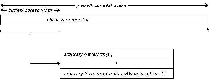
The generator steps through the waveform by adding a deltaPhase between 1 and 2phaseAccumulatorSize-1 to the phase accumulator every clock period (dacPeriod). If the deltaPhase is constant, the generator produces a waveform at a constant frequency that can be calculated as follows:
dacFrequency deltaPhase outputFrequency= ×
arbitraryWaveformSize 2(phaseAccumulatorSize-bufferAddressWidth)
It is also possible to sweep the frequency by continually modifying the deltaPhase. This is done by setting up a deltaPhaseIncrement that the oscilloscope adds to the deltaPhase at specified intervals.
|
ParameterphaseAccumulatorSizebufferAddressWidthdacFrequency dacPeriod (= 1/dacFrequency)
|
Value Original/A/B models 32 bits 14 bits200 MHz 5 ns
|
Value C/D models 32 bits 16 bits 200 MHz 5 ns
|
Applicability picoScope 6402/3/4, including B and D variants
Arguments handle, the handle of the required device
offsetVoltage, the voltage offset, in microvolts, to be applied to the waveform
pkToPk, the peak-to-peak voltage, in microvolts, of the waveform signal
startDeltaPhase, the initial value added to the phase counter as the generator begins to step through the waveform buffer
stopDeltaPhase, the final value added to the phase counter before the generator restarts or reverses the sweep
deltaPhaseIncrement, the amount added to the delta phase value every time the dwellCount period expires. This determines the amount by which the generator sweeps the output frequency in each dwell period.
dwellCount, the time, in units of dacPeriod, between successive additions of deltaPhaseIncrement to the delta phase counter. This determines the rate at which the generator sweeps the output frequency. Minimum value: PS6000_MIN_DWELL_COUNT
* arbitraryWaveform, a buffer that holds the waveform pattern as a set of samples equally spaced in time. If pkToPk is set to its maximum (4 V) and offsetVoltage is set to 0, then:
a sample of 32768 corresponds to 2 V a sample of +32767 corresponds to +2 V
arbitraryWaveformSize, the size of the arbitrary waveform buffer, in samples, from PS6000_MIN_SIG_GEN_BUFFER_SIZE to PS6000_MAX_SIG_GEN_BUFFER_SIZE.
sweepType, determines whether the startDeltaPhase is swept up to the stopDeltaPhase, or down to it, or repeatedly swept up and down. Use one of these values:
PS6000_UP PS6000_DO WN PS6000_UPDO WN PS6000_DOWNUP
operation, see ps6000SigGenBuiltIn
indexMode, specifies how the signal will be formed from the arbitrary waveform data. Single, dual and quad index modes are possible. Use one of these constants:
PS6000_SINGLE PS6000_DUAL PS6000_QUAD
shots, see ps6000SigGenBuiltIn sweeps, see ps6000SigGenBuiltIn triggerType, see ps6000SigGenBuiltIn triggerSource, see ps6000SigGenBuiltInextInThreshold, see ps6000SigGenBuiltIn
Returns pico_OK Pico_INVALID_HANDLE Pico_SIG_GEN_PARAM Pico_SHOTS_SWEEPS_WARNING Pico_NOT_RESPONDING Pico_WARNING_AUX_OUTPUT_CONFLICT Pico_WARNING_EXT_THRESHOLD_CONFLICT Pico_NO_SIGNAL_GENERATOR Pico_SIGGEN_OFFSET_VOLTAGE Pico_SIGGEN_PK_TO_PK Pico_SIGGEN_OUTPUT_OVER_VOLTAGE Pico_DRIVER_FUNCTION Pico_SIGGEN_WAVEFORM_SETUP_FAILED
Pico_AWG_NOT_SUPPORTED (e.g. if device is a 6402/3/4 A/C)
3.9.43.1 AWG index modes
The arbitrary waveform generator supports single, dual and quad index modes to help you make the best use of the waveform buffer.
Single mode. The generator outputs the raw contents of the buffer repeatedly. This mode is the only one that can generate asymmetrical waveforms. You can also use this mode forsymmetrical waveforms, but the dual and quad modes make more efficient use of the buffer memory.
Dual mode. The generator outputs the contents of the buffer from beginning to end, and then does a second pass in the reverse direction through the buffer. This allows you to specify only the first half of a waveform with twofold symmetry, such as a Gaussian function, and let the generator fill in the other half.
Quad mode. The generator outputs the contents of the buffer, then on its second pass through the buffer outputs the same data in reverse order. On the third and fourth passes it does the same but with a negative version of the data. This allows you to specify only the first quarter of a waveform with fourfold symmetry, such as a sine wave, and let the generator fill in the other three quarters.

3.9.44 ps6000SetSigGenBuiltIn
pico_STATUS ps6000SetSigGenBuiltIn
( short handle, long offsetVoltage, unsigned long pkToPk short waveType float startFrequency, float stopFrequency, float increment, float dwellTime, PS6000_SWEEP_TYPE sweepType, PS6000_EXTRA_OPERATIONS operation, unsigned long shots, unsigned long sweeps,PS6000_SIGGEN_TRIG_TYPE triggerType, PS6000_SIGGEN_TRIG_SOURCE triggerSource, short extInThreshold
)
This function sets up the signal generator to produce a signal from a list of built-in waveforms. If different start and stop frequencies are specified, the device will sweep either up, down or up and down.
|
Applicability
|
All modes
|
|
Arguments
|
|
handle, the handle of the required device offsetVoltage, the voltage offset, in microvolts, to be applied to the waveform pkToPk, the peak-to-peak voltage, in microvolts, of the waveform signal waveType, the type of waveform to be generated. PS6000_SINE sine wave PS6000_SQUARE square wavePS6000_TRIANGLE triangle wave PS6000_RAMP_UP rising sawtoothPS6000_RAMP_DOWN falling sawtooth PS6000_SINC sin (x)/x PS6000_GAUSSIANGaussian PS6000_HALF_SINE half (full-wave rectified) sine PS6000_DC_VOLTAGEDC voltage PS6000_WHITE_NOISE white noise startFrequency, the frequency that the signal generator will initially produce. For allowable values seePS6000_SINE_MAX_FREQUENCY and related values. stopFrequency, the frequency at which the sweep reverses direction or returns to the initial frequencyincrement, the amount of frequency increase or decrease in sweep modedwellTime, the time for which the sweep stays at each frequency, in seconds
|
|
Arguments
|
|
sweepType, whether the frequency will sweep from startFrequency tostopFrequency, or in the opposite direction, or repeatedly reverse direction. Use one of these constants: PS6000_UP PS6000_DOWN PS6000_UPDOWN PS6000_DOWNUP operation, selects periodic signal, white noise or PRBS:PS6000_ES_OFF (0) produces the waveform specified by waveType.PS6000_WHITENOISE (1) produces white noise and ignores all settings exceptoffsetVoltage and pkTopk. PS6000_PRBS (2) produces a pseudo-random binary sequence (PRBS) and ignores all settings except offsetVoltage andpkTopk. shots, the number of cycles of the waveform to be produced after a trigger event. If non-zero (from 1 to MAX_SWEEPS_SHOTS), then sweeps must be zero. sweeps, the number of times to sweep the frequency after a trigger event, according to sweepType. If non-zero (from 1 to MAX_SWEEPS_SHOTS), thenshots must be zero. triggerType, the type of trigger that will be applied to the signal generator: PS6000_SIGGEN_RISING trigger on rising edgePS6000_SIGGEN_FALLING trigger on falling edge PS6000_SIGGEN_GATE_HIGHrun while trigger is high PS6000_SIGGEN_GATE_LOW run while trigger is lowtriggerSource, the source that will trigger the signal generator:PS6000_SIGGEN_NONE run without waiting for triggerPS6000_SIGGEN_SCOPE_TRIG use scope trigger PS6000_SIGGEN_AUX_IN use AUX input PS6000_SIGGEN_SOFT_TRIG wait for software trigger provided byps6000SigGenSoftwareControl PS6000_SIGGEN_TRIGGER_RAW reserved If a trigger source other than P6000_SIGGEN_NONE is specified, then either shots orsweeps, but not both, must be non-zero. extInThreshold, not used.
|
|
Returns
|
pico_OK Pico_INVALID_HANDLE Pico_SIG_GEN_PARAM Pico_SHOTS_SWEEPS_WARNING Pico_NOT_RESPONDING Pico_WARNING_AUX_OUTPUT_CONFLICT Pico_WARNING_EXT_THRESHOLD_CONFLICT Pico_NO_SIGNAL_GENERATOR Pico_SIGGEN_OFFSET_VOLTAGE Pico_SIGGEN_PK_TO_PK Pico_SIGGEN_OUTPUT_OVER_VOLTAGE Pico_DRIVER_FUNCTION Pico_SIGGEN_WAVEFORM_SETUP_FAILED Pico_NOT_RESPONDING
|
3.9.45 ps6000SetSimpleTrigger
Pico_STATUS ps6000SetSimpleTrigger
( short handle, short enable, PS6000_CHANNEL source, short threshold, THRESHOLD_DIRECTION direction, unsigned long delay, short autoTrigger_ms
)
This function simplifies arming the trigger. It supports only the LEVEL trigger types and does not allow more than one channel to have a trigger applied to it. Any previous pulse width qualifier is cancelled.
|
Applicability
|
All modes
|
|
Arguments
|
handle: the handle of the required device. enabled: zero to disable the trigger, any non-zero value to set the trigger. source:the channel on which to trigger. threshold: the ADC count at which the trigger will fire. direction: the direction in which the signal must move to cause a trigger. The following directions are supported: ABOVE, BELOW, RISING, FALLING andRISING_OR_FALLING. delay: the time between the trigger occurring and the first sample being taken. autoTrigger_ms: the number of milliseconds the device will wait if no trigger occurs.
|
|
Returns
|
pico_OK Pico_INVALID_HANDLE Pico_USER_CALLBACK Pico_DRIVER_FUNCTION
|
3.9.46 ps6000SetTriggerChannelConditions
Pico_STATUS ps6000SetTriggerChannelConditions
( short handle, PS6000_TRIGGER_CONDITIONS * conditions, short nConditions
)
This function sets up trigger conditions on the scope s inputs. The trigger is defined by one or more PS6000_TRIGGER_CONDITIONS structures that are then ORed together. Each structure is itself the AND of the states of one or more of the inputs. This ANDOR logic allows you to create any possible Boolean function of the scope s inputs.
If complex triggering is not required, use ps6000SetSimpleTrigger .
3.9.46.1 PS6000_TRIGGER_CONDITIONS structure
A structure of this type is passed to ps6000SetTriggerChannelConditions in the conditions argument to specify the trigger conditions, and is defined as follows:
typedef struct tTriggerConditions
{ PS6000_TRIGGER_STATE channelA; PS6000_TRIGGER_STATE channelB; PS6000_TRIGGER_STATE channelC; PS6000_TRIGGER_STATE channelD;PS6000_TRIGGER_STATE external; PS6000_TRIGGER_STATE aux; PS6000_TRIGGER_STATE pulseWidthQualifier;
} PS6000_TRIGGER_CONDITIONS
Each structure is the logical AND of the states of the scope s inputs. The ps6000SetTriggerChannelConditions function can OR together a number of these structures to produce the final trigger condition, which can be any possible Boolean function of the scope s inputs.
The structure is byte-aligned. In C++, for example, you should specify this using the #pragma pack() instruction.
Elements channelA, channelB, channelC, channelD, aux,pulseWidthQualifier: the type of condition that should be applied to each channel. Use these constants: PS6000_CONDITION_DONT_CARE PS6000_CONDITION_TRUE PS6000_CONDITION_FALSE
The channels that are set to PS6000_CONDITION_TRUE or PS6000_CONDITION_FALSE must all meet their conditions simultaneously to produce a trigger. Channels set toPS6000_CONDITION_DONT_CARE are ignored.
external: not used
3.9.47 ps6000SetTriggerChannelDirections
pico_STATUS ps6000SetTriggerChannelDirections
( short handle,PS6000_THRESHOLD_DIRECTION channelA,PS6000_THRESHOLD_DIRECTION channelB,PS6000_THRESHOLD_DIRECTION channelC,PS6000_THRESHOLD_DIRECTION channelD,PS6000_THRESHOLD_DIRECTION ext,PS6000_THRESHOLD_DIRECTION aux
)
This function sets the direction of the trigger for each channel.
PS6000_THRESHOLD_DIRECTION constants PS6000_ABOVE for gated triggers: above the upper threshold PS6000_ABOVE_LOWER for gated triggers: above the lower threshold PS6000_BELOW for gated triggers: below the upper threshold PS6000_BELOW_LOWER for gated triggers: below the lower threshold PS6000_RISING for threshold triggers: rising edge, using upper threshold PS6000_RISING_LOWER for threshold triggers: rising edge, using lower threshold PS6000_FALLING for threshold triggers: falling edge, using upper threshold PS6000_FALLING_LOWER for threshold triggers: falling edge, using lower threshold PS6000_RISING_OR_FALLING for threshold triggers: either edge PS6000_INSIDE for window-qualified triggers: inside window PS6000_OUTSIDE for window-qualified triggers: outside window PS6000_ENTER for window triggers: entering the window PS6000_EXIT for window triggers: leaving the window PS6000_ENTER_OR_EXIT for window triggers: either entering or leaving the windowPS6000_POSITIVE_RUNT for window-qualified triggers PS6000_NEGATIVE_RUNT for window-qualified triggers PS6000_NONE no trigger
3.9.48 ps6000SetTriggerChannelProperties
pico_STATUS ps6000SetTriggerChannelProperties
( short handle,PS6000_TRIGGER_CHANNEL_PROPERTIES * channelPropertiesshort nChannelProperties short auxOutputEnable, long autoTriggerMilliseconds
)
This function is used to enable or disable triggering and set its parameters.
3.9.48.1 TRIGGER_CHANNEL_PROPERTIES structure
A structure of this type is passed to ps6000SetTriggerChannelProperties in the channelProperties argument to specify the trigger mechanism, and is defined as follows:
typedef struct tTriggerChannelProperties
{ short thresholdUpper; unsigned short hysteresisUpper; short thresholdLower; unsigned short hysteresisLower; PS6000_CHANNEL channel;PS6000_THRESHOLD_MODE thresholdMode;
} PS6000_TRIGGER_CHANNEL_PROPERTIES
The structure is byte-aligned. In C++, for example, you should specify this using the #pragma pack() instruction.
Elements thresholdUpper, the upper threshold at which the trigger must fire. This is scaled in 16-bit ADC counts at the currently selected range for that channel.
thresholdUpperHysteresis, the hysteresis by which the trigger must exceed the upper threshold before it will fire. It is scaled in 16bit counts.
thresholdLower, the lower threshold at which the trigger must fire. This is scaled in 16-bit ADC counts at the currently selected range for that channel.
thresholdLowerHysteresis, the hysteresis by which the trigger must exceed the lower threshold before it will fire. It is scaled in 16bit counts.
channel, the channel to which the properties apply. This can be one of the four input channels listed under ps6000SetChannel , or PS6000_TRIGGER_AUX for the AUX input.
thresholdMode, either a level or window trigger. Use one of these constants:
PS6000_LEVEL
PS6000 WINDOW
3.9.49 ps6000SetTriggerDelay
pico_STATUS ps6000SetTriggerDelay
( short handle, unsigned long delay
)
This function sets the post-trigger delay, which causes capture to start a defined time after the trigger event.
3.9.50 ps6000SigGenSoftwareControl
Pico_STATUS ps6000SigGenSoftwareControl
( short handle, short state
)
This function causes a trigger event, or starts and stops gating. It is used when the signal generator is set to SIGGEN_SOFT_TRIG .
3.9.51 ps6000Stop
Pico_STATUS ps6000Stop ( short handle )
This function stops the scope device from sampling data. If this function is called before a trigger event occurs, the oscilloscope may not contain valid data.
Always call this function after the end of a capture to ensure that the scope is ready for the next capture.
|
Applicability
|
All modes
|
|
Arguments
|
handle, the handle of the required device.
|
|
Returns
|
pico_OK Pico_INVALID_HANDLE Pico_USER_CALLBACK Pico_DRIVER_FUNCTION
|
3.9.52 ps6000StreamingReady
typedef void (CALLBACK *ps6000StreamingReady)
( short handle, unsigned long noOfSamples, unsigned long startIndex, short overflow, unsigned long triggerAt, short triggered, short autoStop, void * pParameter
)
This callback function is part of your application. You register it with the driver using ps6000GetStreamingLatestValues, and the driver calls it back when streaming-mode data is ready. You can then download the data using the ps6000GetValuesAsync function.
|
Applicability
|
Streaming mode only
|
|
Arguments
|
handle, the handle of the device returning the samples.noOfSamples, the number of samples to collect. startIndex,an index to the first valid sample in the buffer. This is the buffer that was previously passed to ps6000SetDataBuffer. overflow, returns a set of flags that indicate whether an overvoltage has occurred on any of the channels. It is a bit pattern with bit 0 denoting Channel A. triggerAt, an index to the buffer indicating the location of the trigger point. This parameter is valid only when triggered is nonzero. triggered, a flag indicating whether a trigger occurred. If nonzero, a trigger occurred at the location indicated bytriggerAt. autoStop, the flag that was set in the call tops6000RunStreaming. pParameter, a void pointer passed fromps6000GetStreamingLatestValues. The callback function can write to this location to send any data, such as a status flag, back to the application.
|
|
Returns
|
nothing
|
3.10 Programming examples
Your picoScope SDK installation includes programming examples in various languages and development environments.
3.10.1 C
The C example program is a comprehensive console mode program that demonstrates all of the facilities of the driver.
To compile the program, create a new project for an Application containing the following files:
ps6000con.c
and:
ps6000bc.lib (Borland 32-bit applications) or
ps6000.lib (Microsoft Visual C 32-bit applications)
The following files must be in the compilation directory:
ps6000Api.h
picoStatus.h
and the following file must be in the same directory as the executable:
ps6000.dll
3.10.2 Visual Basic
The Examples/ps6000/ subdirectory of your picoScope installation contains the following files:
ps6000.vbp -project file
ps6000.bas -procedure prototypes
ps6000.frm -form and program
Note: The functions which return a TRUE/FALSE value, return 0 for FALSE and 1 for TRUE, whereas Visual Basic expects 65 535 for TRUE. Check for >0 rather than =TRUE.
3.10.3 Excel
-
Load the spreadsheet ps6000.xls
-
Select Tools | Macro
-
Select GetData
-
Select Run
Note: The Excel macro language is similar to Visual Basic. The functions which return a TRUE/FALSE value, return 0 for FALSE and 1 for TRUE, whereas Visual Basic expects 65 535 forTRUE. Check for >0 rather than =TRUE.
3.10.4 LabVIEW
The SDK contains a library of VIs that can be used to control the picoScope 6000 and some simple examples of using these VIs in streaming mode , block mode and rapid block mode.
The LabVIEW library (picoScope6000.llb) can be placed in the user.lib subdirectory to make the VIs available on the ‘User Libraries’ palette. You must also copy ps6000.dll andps6000wrap.dll to the folder containing your LabView project.
The library contains the following VIs:
picoErrorHandler.vi -takes an error cluster and, if an error has occurred, displays a message box indicating the source of the error and the status code returned by the driver
picoScope6000AdvancedTriggerSettings.vi -an interface for the advanced trigger features of the oscilloscope
This VI is not required for setting up simple triggers, which are configured using
PicoScope6000Settings.vi.
For further information on these trigger settings, see descriptions of the trigger
functions:
ps6000SetTriggerChannelConditionsps6000SetTriggerChannelDirectionsps6000SetTriggerChannelPropertiesps6000SetPulseWidthQualifierps6000SetTriggerDelay
picoScope6000AWG.vi -controls the arbitrary waveform generator
Standard waveforms or an arbitrary waveform can be selected under ‘Wave Type’. There are three settings clusters: general settings that apply to both arbitrary and standard waveforms, settings that apply only to standard waveforms and settings that apply only to arbitrary waveforms. It is not necessary to connect all of these clusters if only using arbitrary waveforms or only using standard waveforms.
When selecting an arbitrary waveform, it is necessary to specify a text file containing the waveform. This text file should have a single value on each line in the range -1 to 1. For further information on the settings, see descriptions of ps6000SetSigGenBuiltIn and ps6000SetSigGenArbitrary.
picoScope6000Close.vi -closes the oscilloscope
Should be called before exiting an application.
picoScope6000GetBlock.vi -collects a block of data from the oscilloscope
This can be called in a loop in order to continually collect blocks of data. The oscilloscope should first be set up by using PicoScope6000Settings.vi. The VI outputs data arrays in two clusters (max and min). If not using aggregation, ‘Min Buffers’ is not used.
picoScope6000GetRapidBlock.vi -collects a set of data blocks or captures from the oscilloscope in rapid block mode
This VI is similar to picoScope6000GetBlock.vi. It outputs two-dimensional arrays for each channel that contain data from all the requested number of captures.
picoScope6000GetStreamingValues.vi -used in streaming mode to get the latest values from the driver
This VI should be called in a loop after the oscilloscope has been set up using picoScope6000Settings.vi and streaming has been started by callingPicoScope6000StartStreaming.vi. The VI outputs the number of samples available and the start index of these samples in the array output by PicoScope6000StartStreaming.vi.
picoScope6000Open.vi -opens a PicoScope 6000 and returns a handle to the device
picoScope6000Settings.vi -sets up the oscilloscope
The inputs are clusters for setting up channels and simple triggers. Advanced triggers can be set up using PicoScope6000AdvancedTriggerSettings.vi.
picoScope6000StartStreaming.vi -starts the oscilloscope streaming
It outputs arrays that will contain samples once picoScope6000GetStreamingValues.vi has returned.
picoStatus.vi -checks the status value returned by calls to the driver
If the driver returns an error, the status member of the error cluster is set to ‘true’ and the error code and source are set.
3.11 Driver status codes
Every function in the ps6000 driver returns a driver status code from the following list of Pico_STATUS values. These definitions can also be found in the file PicoStatus.h, which is included in the PicoScope 6000 Series SDK. Not all codes apply to the PicoScope 6000 Series SDK.
Code (hex) / Symbol and meaning
00 Pico_OK -The PicoScope 6000 is functioning correctly.
01 Pico_MAX_UNITS_OPENED -An attempt has been made to open more than PS6000_MAX_UNITS.
02 Pico_MEMORY_FAIL -Not enough memory could be allocated on the host
machine.
03 Pico_NOT_FOUND -No PicoScope 6000 could be found.
04 Pico_FW_FAIL -Unable to download firmware.
05 Pico_OPEN_OPERATION_IN_PROGRESS
06 Pico_OPERATION_FAILED
07 Pico_NOT_RESPONDING -The PicoScope 6000 is not responding to commands from the PC.
08 Pico_CONFIG_FAIL -The configuration information in the PicoScope 6000 has become corrupt or is missing.
09 Pico_KERNEL_DRIVER_TOO_OLD -The Picopp.sys file is too old to be used with the device driver.
0A Pico_EEPROM_CORRUPT -The EEPROM has become corrupt, so the device will use a default setting.
0B Pico_OS_NOT_SUPPORTED -The operating system on the PC is not supported by this driver.
0C Pico_INVALID_HANDLE -There is no device with the handle value passed.
0D Pico_INVALID_PARAMETER -A parameter value is not valid.
0E Pico_INVALID_TIMEBASE -The timebase is not supported or is invalid.
0F Pico_INVALID_VOLTAGE_RANGE -The voltage range is not supported or is invalid.
10 Pico_INVALID_CHANNEL -The channel number is not valid on this device or no channels have been set.
11 Pico_INVALID_TRIGGER_CHANNEL -The channel set for a trigger is not available on this device.
12 Pico_INVALID_CONDITION_CHANNEL -The channel set for a condition is not available on this device.
13 Pico_NO_SIGNAL_GENERATOR -The device does not have a signal generator.
14 Pico_STREAMING_FAILED -Streaming has failed to start or has stopped without user request.
15 Pico_BLOCK_MODE_FAILED -Block failed to start -a parameter may have been set wrongly.
16 Pico_NULL_PARAMETER -A parameter that was required is NULL.
18 Pico_DATA_NOT_AVAILABLE -No data is available from a run block call.
19 Pico_STRING_BUFFER_TOO_SMALL -The buffer passed for the information was too small.
1A Pico_ETS_NOT_SUPPORTED -ETS is not supported on this device.
1B Pico_AUTO_TRIGGER_TIME_TOO_SHORT -The auto trigger time is less than the time it will take to collect the pre-trigger data.
1C Pico_BUFFER_STALL -The collection of data has stalled as unread data would be overwritten.
1D Pico_TOO_MANY_SAMPLES -Number of samples requested is more than available in the current memory segment.
1E Pico_TOO_MANY_SEGMENTS -Not possible to create number of segments requested.
1F Pico_PULSE_WIDTH_QUALIFIER -A null pointer has been passed in the trigger function or one of the parameters is out of range.
20 Pico_DELAY -One or more of the hold-off parameters are out of range.
21 Pico_SOURCE_DETAILS -One or more of the source details are incorrect.
22 Pico_CONDITIONS -One or more of the conditions are incorrect.
23 Pico_USER_CALLBACK -The driver s thread is currently in the ps6000BlockReady callback function and therefore the action cannot be carried out.
24 pico_DEVICE_SAMPLING -An attempt is being made to get stored data while streaming. Either stop streaming by calling ps6000Stop, or use ps6000GetStreamingLatestValues .
25 pico_NO_SAMPLES_AVAILABLE -because a run has not been completed.
26 Pico_SEGMENT_OUT_OF_RANGE -The memory index is out of range.
27 Pico_BUSY -Data cannot be returned yet.
28 Pico_STARTINDEX_INVALID -The start time to get stored data is out of range.
29 Pico_INVALID_INFO -The information number requested is not a valid number.
2A Pico_INFO_UNAVAILABLE -The handle is invalid so no information is available about the device. Only Pico_DRIVER_VERSION is available.
2B Pico_INVALID_SAMPLE_INTERVAL -The sample interval selected for streaming is out of range.
2D Pico_MEMORY -Driver cannot allocate memory.
2E Pico_SIG_GEN_PARAM -Incorrect parameter passed to signal generator.
34 Pico_WARNING_AUX_OUTPUT_CONFLICT -AUX cannot be used as input and output at the same time.
35 Pico_SIGGEN_OUTPUT_OVER_VOLTAGE -The combined peak to peak voltage and the analog offset voltage exceed the allowable voltage the signal generator can produce.
36 Pico_DELAY_NULL -NULL pointer passed as delay parameter.
37 Pico_INVALID_BUFFER -The buffers for overview data have not been set while streaming.
38 Pico_SIGGEN_OFFSET_VOLTAGE -The analog offset voltage is out of range.
39 Pico_SIGGEN_PK_TO_PK -The analog peak to peak voltage is out of range.
3A Pico_CANCELLED -A block collection has been cancelled.
3B Pico_SEGMENT_NOT_USED -The segment index is not currently being used.
3C Pico_INVALID_CALL -The wrong GetValues function has been called for the collection mode in use.
3F pico_NOT_USED -The function is not available.
40 Pico_INVALID_SAMPLERATIO -The aggregation ratio requested is out of range.
41 Pico_INVALID_STATE -Device is in an invalid state.
42 Pico_NOT_ENOUGH_SEGMENTS -The number of segments allocated is fewer than the number of captures requested.
43 Pico_DRIVER_FUNCTION -You called a driver function while another driver function was still being processed.
45 Pico_INVALID_COUPLING -An invalid coupling type was specified in ps6000SetChannel .
46 pico_BUFFERS_NOT_SET -An attempt was made to get data before a data buffer was defined.
47 pico_RATIO_MODE_NOT_SUPPORTED -The selected downsampling mode (used for data reduction) is not allowed.
49 pico_INVALID_TRIGGER_PROPERTY -An invalid parameter was passed to ps6000SetTriggerChannelProperties .
4A pico_INTERFACE_NOT_CONNECTED -The driver was unable to contact the oscilloscope.
4D Pico_SIGGEN_WAVEFORM_SETUP_FAILED -A problem occurred in ps6000SetSigGenBuiltIn or ps6000SetSigGenArbitrary .
4E pico_FPGA_FAIL
4F Pico_POWER_MANAGER
50 Pico_INVALID_ANALOGUE_OFFSET -An impossible analogue offset value was specified in ps6000SetChannel .
51 pico_PLL_LOCK_FAILED -Unable to configure the PicoScope 6000.
52 Pico_ANALOG_BOARD -The oscilloscope s analog board is not detected, or is not connected to the digital board.
53 Pico_CONFIG_FAIL_AWG -Unable to configure the signal generator.
54 Pico_INITIALISE_FPGA -The FPGA cannot be initialized, so unit cannot be opened.
56 Pico_EXTERNAL_FREQUENCY_INVALID -The frequency for the external clock is not within ±5% of the stated value.
57 Pico_CLOCK_CHANGE_ERROR -The FPGA could not lock the clock signal.
58 Pico_TRIGGER_AND_EXTERNAL_CLOCK_CLASH -You are trying to configure the AUX input as both a trigger and a reference clock.
59 Pico_PWQ_AND_EXTERNAL_CLOCK_CLASH -You are trying to configure the AUX input as both a pulse width qualifier and a reference clock.
5A Pico_UNABLE_TO_OPEN_SCALING_FILE -The scaling file set can not be opened.
5B Pico_MEMORY_CLOCK_FREQUENCY -The frequency of the memory is reporting incorrectly.
5C Pico_I2C_NOT_RESPONDING -The I2C that is being actioned is not responding to requests.
5D Pico_NO_CAPTURES_AVAILABLE -There are no captures available and therefore no data can be returned.
5E Pico_NOT_USED_IN_THIS_CAPTURE_MODE -The capture mode the device is currently running in does not support the current request.
103 Pico_GET_DATA_ACTIVE -Reserved
104 Pico_IP_NETWORKED -The device is currently connected via the IP Network socket and thus the call made is not supported.
105 Pico_INVALID_IP_ADDRESS -An IP address that is not correct has been passed to the driver.
106 Pico_IPSOCKET_FAILED -The IP socket has failed.
107 Pico_IPSOCKET_TIMEDOUT -The IP socket has timed out.
108 Pico_SETTINGS_FAILED -The settings requested have failed to be set.
109 Pico_NETWORK_FAILED -The network connection has failed.
10A Pico_WS2_32_DLL_NOT_LOADED -Unable to load the WS2 dll.
10B Pico_INVALID_IP_PORT -The IP port is invalid.
10C Pico_COUPLING_NOT_SUPPORTED -The type of coupling requested is not supported on the opened device.
10D Pico_BANDWIDTH_NOT_SUPPORTED -Bandwidth limit is not supported on the opened device.
10E Pico_INVALID_BANDWIDTH -The value requested for the bandwidth limit is out of range.
10F Pico_AWG_NOT_SUPPORTED -The device does not have an arbitrary waveform generator.
110 Pico_ETS_NOT_RUNNING -Data has been requested with ETS mode set but run block has not been called, or stop has been called.
111 Pico_SIG_GEN_WHITENOISE_NOT_SUPPORTED -White noise is not supported on the opened device.
112 Pico_SIG_GEN_WAVETYPE_NOT_SUPPORTED -The wave type requested is not supported by the opened device.
116 Pico_SIG_GEN_PRBS_NOT_SUPPORTED -Siggen does not generate pseudorandom bit stream.
117 Pico_ETS_NOT_AVAILABLE_WITH_LOGIC_CHANNELS -When a digital port is enabled, ETS sample mode is not available for use.
118 Pico_WARNING_REPEAT_VALUE -Not applicable to this device.
119 Pico_POWER_SUPPLY_CONNECTED -The DC power supply is connected.
11A Pico_POWER_SUPPLY_NOT_CONNECTED -The DC power supply isn’t connected.
11B Pico_POWER_SUPPLY_REQUEST_INVALID -Incorrect power mode passed for current power source.
11C Pico_POWER_SUPPLY_UNDERVOLTAGE -The supply voltage from the USB source is too low.
11D Pico_CAPTURING_DATA -The device is currently busy capturing data.
11F Pico_NOT_SUPPORTED_BY_THIS_DEVICE -A function has been called that is not supported by the current device variant.
120 Pico_INVALID_DEVICE_RESOLUTION -The device resolution is invalid (out of range).
121 Pico_INVALID_NUMBER_CHANNELS_FOR_RESOLUTION -The number of channels which can be enabled is limited in 15 and 16-bit modes
122 Pico_CHANNEL_DISABLED_DUE_TO_USB_POWERED -USB Power not sufficient to power all channels.
3.12 Enumerated types and constants
Here are the enumerated types used in the PicoScope 6000 Series SDK, as defined in the file ps6000Api.h . We recommend that you refer to these constants by name unless your programming language allows only numerical values.
#define PS6000_MAX_OVERSAMPLE_8BIT 256
#define PS6000_MAX_VALUE 32512 #define PS6000_MIN_VALUE -32512
#define MAX_PULSE_WIDTH_QUALIFIER_COUNT 16777215L
#define MAX_SIG_GEN_BUFFER_SIZE 16384 #define MIN_SIG_GEN_BUFFER_SIZE 10 #define MIN_DWELL_COUNT 10 #define MAX_SWEEPS_SHOTS ((1 << 30) -1)
#define MAX_WAVEFORMS_PER_SECOND 1000000
#define MAX_ANALOGUE_OFFSET_50MV_200MV 0.500f #define MIN_ANALOGUE_OFFSET_50MV_200MV -0.500f #define MAX_ANALOGUE_OFFSET_500MV_2V 2.500f #define MIN_ANALOGUE_OFFSET_500MV_2V -2.500f#define MAX_ANALOGUE_OFFSET_5V_20V 20.f #define MIN_ANALOGUE_OFFSET_5V_20V -20.f
#define PS6000_MAX_ETS_CYCLES 250 #define PS6000_MAX_INTERLEAVE 50
typedef enum enPS6000ExternalFrequency
{ PS6000_FREQUENCY_OFF, PS6000_FREQUENCY_5MHZ, PS6000_FREQUENCY_10MHZ, PS6000_FREQUENCY_20MHZ, PS6000_FREQUENCY_25MHZ, PS6000_MAX_FREQUENCIES
} PS6000_EXTERNAL_FREQUENCY;
typedef enum enPS6000BandwidthLimiter
{ PS6000_BW_FULL, PS6000_BW_20MHZ, PS6000_BW_25MHZ,
} PS6000_BANDWIDTH_LIMITER;
typedef enum enPS6000Channel
{ PS6000_CHANNEL_A, PS6000_CHANNEL_B, PS6000_CHANNEL_C, PS6000_CHANNEL_D, PS6000_EXTERNAL, PS6000_MAX_CHANNELS = PS6000_EXTERNAL, PS6000_TRIGGER_AUX, PS6000_MAX_TRIGGER_SOURCES
} PS6000_CHANNEL;
typedef enum enPS6000ChannelBufferIndex
{ PS6000_CHANNEL_A_MAX, PS6000_CHANNEL_A_MIN, PS6000_CHANNEL_B_MAX, PS6000_CHANNEL_B_MIN, PS6000_CHANNEL_C_MAX, PS6000_CHANNEL_C_MIN, PS6000_CHANNEL_D_MAX, PS6000_CHANNEL_D_MIN,PS6000_MAX_CHANNEL_BUFFERS
} PS6000_CHANNEL_BUFFER_INDEX;
typedef enum enPS6000Range
{ PS6000_10MV, PS6000_20MV, PS6000_50MV, PS6000_100MV,
PS6000_200MV,PS6000_500MV,PS6000_1V,PS6000_2V,PS6000_5V,PS6000_10V,PS6000_20V,PS6000_50V,PS6000_MAX_RANGES
} PS6000_RANGE;
typedef enum enPS6000Coupling
{ PS6000_AC,PS6000_DC_1M,PS6000_DC_50R
} PS6000_COUPLING;
typedef enum enPS6000EtsMode {PS6000_ETS_OFF,PS6000_ETS_FAST,PS6000_ETS_SLOW,PS6000_ETS_MODES_MAX } PS6000_ETS_MODE;
typedef enum enPS6000TimeUnits {PS6000_FS,PS6000_PS,PS6000_NS,PS6000_US,PS6000_MS,PS6000_S,PS6000_MAX_TIME_UNITS,} PS6000_TIME_UNITS;
typedef enum enPS6000SweepType
{ PS6000_UP,PS6000_DOWN,PS6000_UPDOWN,PS6000_DOWNUP,PS6000_MAX_SWEEP_TYPES
} PS6000_SWEEP_TYPE;
typedef enum enPS6000WaveType
{ PS6000_SINE,PS6000_SQUARE,PS6000_TRIANGLE,PS6000_RAMP_UP,PS6000_RAMP_DOWN,PS6000_SINC,PS6000_GAUSSIAN,PS6000_HALF_SINE,PS6000_DC_VOLTAGE,PS6000_WHITE_NOISE,PS6000_MAX_WAVE_TYPES
} PS6000_WAVE_TYPE;
typedef enum enPS6000ExtraOperations
{ PS6000_ES_OFF,PS6000_WHITENOISE,PS6000_PRBS // Pseudo-Random Bit Stream
|
} PS6000_EXTRA_OPERATIONS;
|
|
#define PS6000_SINE_MAX_FREQUENCY #define PS6000_SQUARE_MAX_FREQUENCY #define PS6000_TRIANGLE_MAX_FREQUENCY #define PS6000_SINC_MAX_FREQUENCY #define PS6000_RAMP_MAX_FREQUENCY #define PS6000_HALF_SINE_MAX_FREQUENCY #define PS6000_GAUSSIAN_MAX_FREQUENCY #define PS6000_MIN_FREQUENCY
|
20000000.f 20000000.f 20000000.f 20000000.f 20000000.f 20000000.f 20000000.f 0.03f
|
|
typedef enum enPS6000SigGenTrigType { PS6000_SIGGEN_RISING,PS6000_SIGGEN_FALLING,
|
|
PS6000_SIGGEN_GATE_HIGH, PS6000_SIGGEN_GATE_LOW
} PS6000_SIGGEN_TRIG_TYPE;
typedef enum enPS6000SigGenTrigSource
{ PS6000_SIGGEN_NONE,PS6000_SIGGEN_SCOPE_TRIG,PS6000_SIGGEN_AUX_IN,PS6000_SIGGEN_EXT_IN,PS6000_SIGGEN_SOFT_TRIG,PS6000_SIGGEN_TRIGGER_RAW
} PS6000_SIGGEN_TRIG_SOURCE;
typedef enum enPS6000IndexMode
{ PS6000_SINGLE,PS6000_DUAL,PS6000_QUAD,PS6000_MAX_INDEX_MODES
} PS6000_INDEX_MODE;
typedef enum enPS6000ThresholdMode
{ PS6000_LEVEL,PS6000_WINDOW
} PS6000_THRESHOLD_MODE;
typedef enum enPS6000ThresholdDirection
{ PS6000_ABOVE,PS6000_BELOW,PS6000_RISING,PS6000_FALLING,PS6000_RISING_OR_FALLING,PS6000_ABOVE_LOWER,PS6000_BELOW_LOWER,PS6000_RISING_LOWER,PS6000_FALLING_LOWER,
// Windowing using both thresholds
PS6000_INSIDE = PS6000_ABOVE, PS6000_OUTSIDE = PS6000_BELOW, PS6000_ENTER = PS6000_RISING, PS6000_EXIT = PS6000_FALLING, PS6000_ENTER_OR_EXIT = PS6000_RISING_OR_FALLING,PS6000_POSITIVE_RUNT = 9,
PS6000_NEGATIVE_RUNT,
// no trigger set
PS6000_NONE = PS6000_RISING } PS6000_THRESHOLD_DIRECTION;
typedef enum enPS6000TriggerState
{ PS6000_CONDITION_DONT_CARE,PS6000_CONDITION_TRUE,PS6000_CONDITION_FALSE,PS6000_CONDITION_MAX
} PS6000_TRIGGER_STATE;
typedef enum enPS6000RatioMode
{ PS6000_RATIO_MODE_NONE,PS6000_RATIO_MODE_AGGREGATE = 1,PS6000_RATIO_MODE_AVERAGE = 2,PS6000_RATIO_MODE_DECIMATE = 4,PS6000_RATIO_MODE_DISTRIBUTION = 8
} PS6000_RATIO_MODE;
typedef enum enPS6000PulseWidthType
{ PS6000_PW_TYPE_NONE,PS6000_PW_TYPE_LESS_THAN,PS6000_PW_TYPE_GREATER_THAN,PS6000_PW_TYPE_IN_RANGE,PS6000_PW_TYPE_OUT_OF_RANGE
} PS6000_PULSE_WIDTH_TYPE;
3.13 Numeric data types
Here is a list of the sizes and ranges of the numeric data types used in the PicoScope 6000 Series API.
|
Type Bits Signed or unsigned?
|
|
short 16 signed
|
|
enum 32 enumerated
|
|
nt 32 signed
|
|
ong 32 signed
|
|
unsigned long 32 unsigned
|
|
float 32 signed (IEEE 754)
|
|
int64 64 unsigned
|
Glossary
Callback. A mechanism that the PicoScope 6000 driver uses to communicate asynchronously with your application. At design time, you add a function (a callback function) to your application to deal with captured data. At run time, when you request captured data from the driver, you also pass it a pointer to your function. The driver then returns control to your application, allowing it to perform other tasks until the data is ready. When this happens, the driver calls your function in a new thread to signal that the data is ready. It is then up to your function to communicate this fact to the rest of your application.
Device Manager. A Windows program that displays the current hardware configuration of your computer. Right-click My Computer, choose Properties, then click the Hardware tab and the Device Manager button.
Driver. A program that controls a piece of hardware. The driver for the PicoScope 6000 Series oscilloscopes is supplied in the form of a 32-bit Windows DLL, ps6000.dll. This is used by the PicoScope software, and by user-designed applications, to control the oscilloscopes.
PC Oscilloscope. A virtual instrument formed by connecting a PicoScope 6000 Series oscilloscope to a computer running the PicoScope software.
PicoScope 6000 Series. A range of PC Oscilloscopes from Pico Technology. The common features include 5 GS/s maximum sampling rate and 8-bit resolution. The scopes are available with a range of buffer sizes up to 2 GS.
PicoScope software. A software product that accompanies all Pico PC Oscilloscopes. It turns your PC into an oscilloscope, spectrum analyzer.
PRBS (pseudo-random binary sequence). A very long, fixed, repeating sequence of binary digits that appears random when analyzed over a time shorter than the repeat period. The waveform swings between two values: logic high (binary 1) and logic low (binary 0).
USB 1.1. Universal Serial Bus (USB) is a standard port that enables you to connect external devices to PCs. A USB 1.1 port uses signaling speeds of up to 12 megabits per second, much faster than an RS-232 port.
USB 2.0. The second generation of USB interface. The port supports a data transfer rate of up to 480 megabits per second.
USB 3.0. A USB 3.0 port uses signaling speeds of up to 5 gigabits per second and is backwards-compatible with USB 2.0 and USB 1.1.
Distribution 38
Index
Downsampling 37 maximum ratio 28 modes 38 A Driver 6 status codes 90
AC coupling 57 Aggregation 17, 38 Analog offset 27, 57 E API function calls 21
Enabling channels 57
Arbitrary waveform generator 72
Enumerated types 94
index modes 74
Enumerating oscilloscopes 25
Averaging 38
ETS overview 15 B setting time buffers 65, 66 setting up 64
Bandwidth limiter 57
using 16
Block mode 7, 8, 9
Excel macros 87
asynchronous call 9
External clock 67
callback 22 polling status 46 running 53 F Buffers
Function calls 21
overrun 7
Functions ps6000BlockReady 22 C ps6000CloseUnit 23 ps6000DataReady 24
C programming 87
ps6000EnumerateUnits 25
Callback function
ps6000FlashLed 26
block mode 22
ps6000GetAnalogueOffset 27
for data 24
ps6000GetMaxDownSampleRatio 28
streaming mode 86
ps6000GetNoOfCaptures 29
Channels
ps6000GetStreamingLatestValues 30
enabling 57
ps6000GetTimebase 31
settings 57
ps6000GetTimebase2 32
Clock, external 67
ps6000GetTriggerTimeOffset 33
Closing units 23
ps6000GetTriggerTimeOffset64 34
Company information 3
ps6000GetUnitInfo 35
Constants 94
ps6000GetValues 37
Contact details 3
ps6000GetValuesAsync 39
Coupling type, setting 57 ps6000GetValuesBulk 40 ps6000GetValuesBulkAsync 41
D
ps6000GetValuesOverlapped 42 Data acquisition 17 ps6000GetValuesOverlappedBulk 43 Data buffers ps6000GetValuesTriggerTimeOffsetBulk 44 declaring 60 ps6000GetValuesTriggerTimeOffsetBulk64 45 declaring, aggregation mode 62 ps6000IsReady 46 declaring, rapid block mode 61 ps6000IsTriggerOrPulseWidthQualifierEnabled 47
setting up 63
ps6000MemorySegments 48
DC coupling 57
ps6000NoOfStreamingValues 49
Decimation 38
ps6000OpenUnit 50
Disk space 4
ps6000OpenUnitAsync 51
Functions ps6000OpenUnitProgress 52 ps6000RunBlock 53 ps6000RunStreaming 55 ps6000SetChannel 57 ps6000SetDataBuffer 60 ps6000SetDataBufferBulk 61 ps6000SetDataBuffers 62 ps6000SetDataBuffersBulk 63 ps6000SetEts 64 ps6000SetEtsTimeBuffer 65 ps6000SetEtsTimeBuffers 66 ps6000SetExternalClock 67 ps6000SetNoOfCaptures 68 ps6000SetPulseWidthQualifier 69 ps6000SetSigGenArbitrary 72 ps6000SetSigGenBuiltIn 75 ps6000SetSimpleTrigger 77 ps6000SetTriggerChannelConditions 78 ps6000SetTriggerChannelDirections 80 ps6000SetTriggerChannelProperties 81 ps6000SetTriggerDelay 83 ps6000SigGenSoftwareControl 84 ps6000Stop 85 ps6000StreamingReady 86
H
Hysteresis 82
I
Information, reading from units 35 Input range, selecting 57 Installation 5
L
LabVIEW 88 LED flashing 26
M
Macros in Excel 87 Memory in scope 8 Memory segments 48 Microsoft Windows 4 Multi-unit operation 20
N
Numeric data types 97
O
One-shot signals 15
Opening a unit 50 checking progress 52 without blocking 51
Operating system 4 Oversampling 19
P
Pico Technical Support 3 Pico_STATUS enum type 90 Picopp.inf 6 Picopp.sys 6 PicoScope 6000 Series 1 PicoScope software 5, 6, 90 Processor 4 Programming
C 87 Excel 87 LabVIEW 88 Visual Basic 87
PS6000_CONDITION_ constants 71, 79 PS6000_LEVEL constant 82 PS6000_LOST_DATA constant 7 PS6000_MAX_VALUE constant 7 PS6000_MIN_VALUE constant 7 PS6000_PWQ_CONDITIONS structure 71 PS6000_TIME_UNITS constant 33 PS6000_TRIGGER_CHANNEL_PROPERTIES
structure 82 PS6000_TRIGGER_CONDITIONS structure 79 PS6000_WINDOW constant 82 Pulse-width qualifier 69
conditions 71 requesting status 47
R
Rapid block mode 10
setting number of captures 68 Resolution, vertical 19 Retrieving data 37, 39
block mode, deferred 42 rapid block mode 40 rapid block mode with callback 41 rapid block mode, deferred 43 stored 18 streaming mode 30
Retrieving times rapid block mode 44, 45
|
PicoScope 6000 Series Programmer s Guide
|
|
|
101
|
|
S Sampling rate maximum 8 Scaling 7 Serial numbers 25 Signal generator 9 arbitrary waveforms 72 built-in waveforms 75 software trigger 84 Software licence conditions 2 Status codes 90 Stopping sampling 85 Streaming mode 7, 17 callback 86 getting number of samples 49 retrieving data 30 running 55 using 17 Synchronising units 20 System memory 4 System requirements 4 TTechnical support 3 Threshold voltage 7 Time buffers setting for ETS 65, 66 Timebase 19 calculating 31, 32 Trademarks 2 Trigger 7 channel properties 81 conditions 78, 79 delay 83 directions 80 pulse-width qualifier 69 pulse-width qualifier conditions 71 requesting status 47 setting up 77 time offset 33, 34 UUSB 4, 6 changing ports 5 hub 20 V Vertical resolution 19
|
Visual Basic programming Voltage ranges 7 selecting 57
|
87
|
|
|
Copyright © 2009-2013 Pico Technology Ltd. All rights reserved.
|
|
|
ps6000pg.en r9
|
pico Technology
James House Colmworth Business Park ST. NEOTS Cambridgeshire PE19 8YP United Kingdom Tel: +44 (0) 1480 396 395 Fax: +44 (0) 1480 396 296 www.Picotech.com
ps6000pg.en r9 02.09.13
Copyright © 2009-2013 Pico Technology Ltd. All rights reserved.
pico
参数资料:
|
ps6000pg.en-编程指南ps6000pg.en,编程指南


|
价格列表:
ps6000pg.en-编程指南ps6000pg.en,编程指南
|
|
相关产品:
ps6000pg.en-编程指南ps6000pg.en,编程指南
|
|
|
|
|
 收藏葩星
收藏葩星

 400-878-1895